|
|||||||||||||
 |
|||||||||||||
The Radio Physics Course: Resistances in Radio |
|||||||||||||
The Radio Physics Course: Resistances in Radio Lesson Nine (Continued from Lesson Eight) Resistances in Radio, Resistance alloys, How the resistance units are actually made and used . This series deals with the study of the physical aspects of radio phenomena. It contains information of particular value to physics teachers and students in high schools and colleges. The Question Box aids teachers in laying out current class assignments. By Alfred A. Ghirardi*
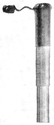
Vitrified Resistor Figure 1 - Shows the stages in building up this form of resistance. At the bottom is the porcelain tube upon which is wound a resistance wire shown at center. At top is the enamel coating which is then baked on after the terminal has been attached. Since the temperature of a conductor may be changed by the weather conditions or by the heat developed in the wire itself due to the passage of current through it, the temperature must be taken into account when calculating the resistance if accurate results are desired. The resistance of pure metals and most alloys increases as the temperature rises. The resistance of carbon and electrolytes (fluid conductors) decreases as their temperature rises. The amount of change of resistance varies with the different conductors, but for pure metals the increase in resistance is nearly 0.4% for each change of one degree Centigrade. Manganin is an alloy of 84% copper, 12% nickel and 4% manganese, developed especially for use in the shunts of ammeters and for precision resistances. Therlo is a similar alloy. Its change in resistance per degree is one part in 100,000. "Constantin" is another alloy whose resistance does not change materially. It consists of approximately 60% copper and 40% nickel. It is used in rheostats and measuring instruments. The amount in ohms that a piece of the material having a resistance of one ohm changes for each change of one degree in temperature is known as the temperature coefficient of resistance ("a"). Thus if a conductor has a resistance of one ohm at 20° C temperature, it will have a resistance of one ohm plus the amount equal to this coefficient at 21° C At 19° C it would have a resistance of one ohm minus the coefficient, etc. The average temperature coefficient between 0° and 100° C and 32° and 212° F. is roughly the same for all pure metals and is about 0.004 per degree Centigrade, or 0.0023 per degree Fahrenheit (since one degree C represents a larger change in temperature than one degree F). The temperature coefficient for annealed copper is 0.00210 at an initial temperature of 68° F (on the Fahrenheit scale), or 0.00377 at an initial temperature of 20° C (on the Centigrade scale). The value of the temperature coefficients of the various resistance alloys used in radio work for winding fixed or variable resistors must be obtained from the manufacturers of the resistance wire in any case when exact calculations are to be made. Since the specific resistance of the conducting materials is usually given for the material at standard temperature of 20° C, the formula must be altered if we are to take into account the change of resistance due to the fact that the conductor may be at a temperature above or below 20° C in actual practice. To calculate the true resistance of any metallic conductor at any temperature (up to 100° C) use the formula
where R = resistance of the conductor in ohms at operating temperature. k = specific resistance of the conductor at 20° C L = length of conductor in feet. C.M. = cross section area of conductor in circular mils. a = temperature coefficient of the material per degree C. t = difference in degrees between the operating temperature and the standard temperature at which the specific resistance k is specified (20° C in most cases). The ± sign inside the bracket means that if the temperature of the conductor is above the standard of 20° C. the resistance increases so the plus sign is used. If the temperature is below 20° C the resistance is less and the minus sign is used. Example: A piece of No. 18 B. & S. gauge copper wire 600 feet long is wound up to form a circular field coil for an electro-dynamic loudspeaker. When the normal current flows through the coil its temperature rises to 60° C What is the exact resistance of the coil during normal operation? Solution: From the copper wire table we find that a No. 18 wire has a cross-section area of 1620 circular mils. The specific resistance of annealed copper is 10.35 at 20° C. Its temperature coefficient is 0.00377 per degree C. "t" in the formula is therefore equal to 60 - 20 = 40 degrees. Substituting these values, we obtain
from which R = 4.37 ohms. Ans. Resistors in Radio Equipment
Wire-wound Resistors of Various Types Figure 2 - Here are shown several forms of resistors of the vitreous enamel types, the smaller ones with screw terminals attached. The two lower resistors are equipped with the standard Edison lamp socket bases. At right, second from top, is a completed resistor similar to that shown in Figure 1. The resistor H contains a number of taps that make it suitable for voltage divider work. It is equipped with mounting legs. There is naturally a certain amount of resistance in every electrical circuit due to the resistance of the connecting wires, joints, contacts, etc. The resistance of a circuit can be kept low by making it as short as possible, using a good electrical conductor (such as copper), and making its cross-section area large. (Due to the fact that very high frequency currents travel only through a thin surface layer of the wire, "skin effect," wires for conducting this type of current are often made up of a number of very small conductors insulated from each other by an enamel, cotton or silk covering. (This is called Litzendraht wire.) In radio equipment resistance is purposely introduced at various places in the circuits in order to reduce or control the amount of current flowing, reduce the effective voltage applied to a device, or cause differences of potential which are utilized for some definite purpose (C bias resistors), etc. A resistor is a device whose purpose is to intentionally provide resistance in an electrical circuit. Resistors may be made either fixed or adjustable (variable). Fixed resistors are those whose value cannot be changed readily while in use. Adjustable resistors may be varied in value. Fixed resistors are used in the filament circuits of battery-operated vacuum tubes, in the voltage dividers of B eliminators, for leaks, resistance couplings for furnishing grid or C bias voltages, etc. Variable resistances are not used as much in radio receivers nowadays as they formerly were, due to the tendency to eliminate as many control knobs from the panels as possible. They are still employed as rheostats, potentiometers, volume controls, etc. Vitreous enameled resistors are used extensively in power packs of radio receivers. They are made by space-winding the resistance wire on a special porcelain tube base. The base, including the terminal connections, is then coated with a powdered glassy enamel and fired at red heat. The result is a resistor unit covered with a vitreous enamel coating which protects the fine resistance wire from mechanical injury and serves as an excellent heat conductor to rapidly conduct the heat from the resistive element to the outside surface. This construction permits the finest resistance wire to be used without danger of oxidation or other chemical depreciation. The enamel also holds the resistance wire in place without any mechanical strain, and no strains can be set up by heating or cooling, as the vitreous enamel and the wire expand and contract together. Figure 1 shows a resistor of this type during the various stages of manufacture, from the bare porcelain base tube at one end to the completely vitrified resistance winding at the other end. This is a voltage divider resistance used in power packs. Special resistance wires made from alloys of nickel and iron have been developed for winding these resistors. They have very low temperature coefficients of resistance and therefore their resistance does not change very much when they get warm in service. Several resistors of this type made up in special forms for use in radio receivers are shown in Figure 2. Resistor H is variable in value in steps.
Question Box Physics and science instructors will find these review questions and the "quiz" questions below useful as reading assignments for their classes. For other readers the questions provide an interesting pastime and permit a check on the reader's grasp of the material presented in the various articles in this issue. The "Review Questions" cover material in this month's installment of the Radio Physics Course. The "General Quiz" questions are based on other articles in this issue as follows: The "Twin-Grid" Tube, A Modern Quartz-Crystal Receiver, Latest Short-Wave Converter, With the Experimenter, Phenomena Underlying Radio, A 16.5 to 550-Meter "Super" of Radical Circuit Design, The March of Television, Radio Fever, Two New Tubes.
Review Questions 1. Calculate the power supplied to the filament of a 280 type rectifier tube which takes a current of 2 amps. at 5 volts. 2. State the four factors upon which the resistance of a conductor depends and explain just how each one affects the resistance. 3. The diameter of 1000 ft. of No. 24 B. & S. copper 'wire, used [or the winding on a filament transformer is .0201 inches. What is its diameter in mils? What is the circular mil area? If the specific resistance of copper wire is 10.35 at 20° C, what will be the resistance of this wire at a temperature of 20° C? 4. What is the resistance of the wire in problem 3 at all operating temperature of 80° C if the temperature coefficient of copper is 0.004? 5. From the table of specific resistances of carious materials in your book, write down the ten metals having the highest specific resistances. Next to each, write down how many times greater its resistance is than that of annealed copper. 6. Describe the construction of the vitreous enameled type of wire-wound resistor. 7. Describe the construction of two forms of high resistors used in radio receivers in places where very little current will be flowing. 8. Describe the construction of a variable high resistor designed to carry a small amount of current without overheating. What is the purpose of the flaked mica in this? 9. Describe the construction of a variable wire-wound resistor. 10. What installation conditions affect the power in watts which a resistor can dissipate? 11. Draw a symbol for (a) a fixed resistor, (b) a variable resistor, (c) a resistor tapped at the middle, (d) a resistor tapped at three places.
General Quiz on This Issue 1. How do strong ultra-short radio waves affect the human body? 2. What is a harmonic generator? 3. What is the electrophorus? 4. What does the term "definition" mean as applied to television? Why is it important? 5. The use of a quartz-plate circuit in a superheterodyne i.f. amplifier admittedly attenuates the higher audio frequencies. By what method is this attenuation overcome in the latest design of receivers of this type? 6. Explain why a Stenode receiver tends to reduce background noise. 7. How are the grids placed, in one of the newest tube designs, to make the tube characteristic identical when either grid is in the circuit? 8. Why does this tube lend itself particularly well to automatic volume control? 9. What forces of conditions may upset the normal balance of charges in the atom? 10. What are the advantages of incorporating one i.f. stage in a superheterodvne type short-wave converter? 11. What Principle, commonly used in measuring resistance, is employed im one type of simplified remote control, and how is this principle utilized? 12. How may signals of high frequencies be concerted to signals of lower radio frequencies? 13. How may two ribbons of silk be made to generate 1,000,000 volts? 14. What are the advantages of the r.f. pentode tube?
*Radio Technical Pub. Co., Publishers Radio Physics Course.
Posted February 2, 2021 |
|||||||||||||
 |
|||||||||||||
|
|||||||||||||


|
||||||||||||||||||||||||||||||||||||


