|
|||||||||||||
 |
|||||||||||||
Radio Seeks Black Gold |
|||||||||||||
Discovering new oil reserves usually takes more than the good fortune of being out shoot'n at some food, when up from the ground come a bubbl'n crude - oil that is, black gold, Texas tea. Over the decades, chance has been replaced by high tech prospecting methods including ground-penetrating radar, radio and acoustic wave sounding, ultrasonic transponders, and even satellite sensors that discern telltale variations in gravitational pull, and magnetic fields. This article from a 1948 issue of Radio News describes the use of radio for coordinating activities between the point of explosions and where recording equipment is located, all of which required the transmission of precise timing signals. Oil - the life blood of industrialization - is now being located by modern electronic equipment. By T.A. Patterson., Jr.
Fig. 1 - Flat bottomed boat is used for stringing pickup cable in swamp areas. Deep in our Southwest territory which, roughly, comprises the states of Louisiana, Texas, Oklahoma, and New Mexico, the sensitive fingers of radio inspired equipment are probing the vast subterranean areas for new deposits of one of our most valuable resources. Even those who have heard the names geophysics, doodle-bugging, or seismograph survey seldom realize the all-important part electronics has played in the search for one of earth's richest treasures - oil - truly a black gold, a bonanza, without which the wheels of industry would be paralyzed. The many complex activities of the petroleum industry, which include scouting, leasing, royalties and mineral rights, drilling, spacing, producing, wildcat ventures, and the like, have become heavily dependent on this comparatively new super-sleuth of the deep, for on the shoulders of the modern geophysicist has fallen the burden of predetermination of substructure formations. Before delving into the applications of electronics in petroleum's realm, we should first study very briefly the term "geophysics" and the relation of oil bearing structures to the earth's conformities. Webster defines the term "geophysics" as "The physics of the earth, or the science treating of the agencies which modify the earth." The earth, over its span of life, has been built up of a multitude of composite layers of various materials, and, by structural changes, has exposed certain layers, hidden others, and in some places shifted the strata until they no longer match. This resultant configuration is known basically as a fault, of which there are many kinds and types. Fig. 4A illustrates various types of structures of the substrata and. shows possible points where oil may be found. The structures in which the porous stratum is shaped like an inverted bowl are called anticlines. Much of the world's known oil lies in such reservoirs.
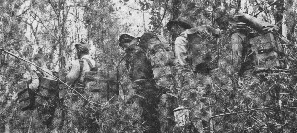
Fig. 2 - Part of seismograph crew on typical swamp operation. Where work is performed in part dry and part submerged country, all equipment must be back-packed.
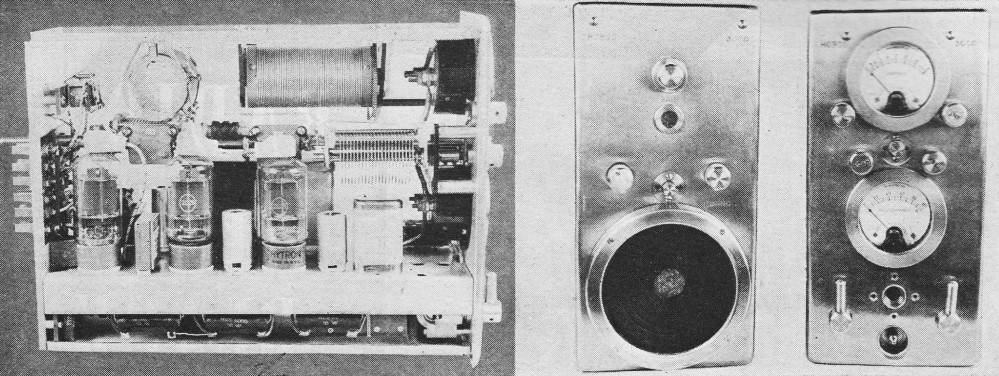
Fig. 3 - Front view of typical two-way radio equipment and an open side view of the transmitter portion. This communications link plays an important role in coordinating operations and relaying the shot break marker.
Fig. 4. (A) Cross-section of earth structure to a depth of approximately 5000 feet and a width of 2 miles. Darkened areas are gas pockets, usually under considerable pressure, lying above the oil pools. (B) Artist's sketch showing cross-section of earth with relative location of geophones to shot hole, and a record superimposed to show sub-surface strata kicks on the record. Numbers 1 and 6 show relative pickup to the corresponding record trace: T is the timing trace and X is the shot break point. Note the additional time required for the signal to reach phone 6 (Y). Using the above data as a rough guide, we can now take up the process of seismograph survey as applied to the science of geophysics. First let us go over the entire process of obtaining a record of the earth's variation, then the theory can be broken down into its component parts and studied individually to determine the electronic era's part in the technique. Using Fig. 4B as a reference guide, the setup or spread is made as follows: In a straight line, predetermined and marked by civil surveys and maps, the shot point and recording truck with its geophones are set up. A charge of dynamite is set off at the shot point with the resulting waves reverberating downward to the hard rock or limestone base beds, then returning to the surface as an echo wave to be picked up by the geophones and recorded photographically. The millisecond time constants are the fundamental keynotes in determining the information being sought. Fig. 4B also shows a corresponding section of the seismic record showing the relative "kicks" from various rock strata. To an untrained eye, these "wriggly snakes" are so much hash, but, to the eye of an old hand in the game, the hieroglyphics immediately become a language of the earth, with syllables and punctuations as plain as our own native tongue. With a slight background of the general field, we can now explore the component parts for a study of the role radio plays in this dramatic search for hidden wealth. To prove a point, it might be mentioned that the recording truck uses upward of 150 tubes in actual circuit functions. As mentioned before, the split second timing must be perfectly accurate, so communication between the shot point (where the dynamite charge is set off), and the recording instruments is an absolute necessity. This is done in one of two ways, depending upon the location and type of area being surveyed. Communication is established between the two points by telephone or by radio (see Fig. 3), and, by either system, a contact is made for transmission of the exact time marker or "shot break" as it is called. One manner of obtaining this marker is by tying a piece of light wire about the dynamite cap used to set off the blast and, by long leads, connecting this wire in series with the transmitter keying circuit or the telephone line. When the charge is shot off, the radio or the phone is killed, thereby removing the voltage at the other end and producing a resultant kick. Another system for handling this necessity calls for a modification of the blasting box. It is rebuilt in such a manner that the current generated by the magneto is not at once applied to the dynamite-cap, but only when the handle reaches the bottom and hits a micro-switch. One side of the firing line runs through a small transformer, the secondary of which is in series with the phone line or modulation transformer of the radio. The sudden pulse gives a clean sharp break point, readily discernible on the final record.
Fig. 5 - Typical seismograph shot showing blowout when hole is left uncovered. Such blowouts are controlled when they are located near highways or buildings. The instrument picking up these reverberations from the earth is known as a geophone, and is most simply identified by describing it as a moving case microphone as seen in Fig. 6. There may be from 6 to 36 of these used, depending on general conditions such as the type of spread, penetration desired, etc. The average recording unit uses 12 or 18, though at times when ground conditions are bad, two are used at each location to provide a stronger signal. There are several types of "jugs" used, usually of the individual company's own design, incorporating various types of movements, impedances, and systems for damping. The typical geophone has a natural frequency of from 10 to 40 cycles. It is nearly critically damped and may have an internal impedance of from 10 to 1000 ohms. The output voltage of a "jug" having 100 ohms impedance ranges from 20 to 100 volts per inch amplitude of motion. Since this apparently large output rating is in terms of measurement units, it must be emphatically pointed out that average movement for a weak reflected signal is in the order of 1 microinch. The output of each unit is carried to the recording equipment over a two conductor cable which is generally a heavily sheathed copper and steel type (Fig. 6) to withstand the rough treatment of field work. These cables are stored, when not in use, on large reels on the back of the recording truck. These reels are powered by electric starter type motors or a power take-off gear box on the truck's transmission such as the one mounted on the rear of the truck in Fig. 7. In many portions of Louisiana and Florida, nearly impenetrable swamps (Fig. 1) require all gear to be carried on the crew's backs (Fig. 2) to some of the locations. This necessitates a very lightweight waterproof cable, which, of course, gains in weight and space saving, but at a sacrifice of longevity. The geophone signals are fed into the instrument panel junction box and thence to the control panel, where, by multiple controls, they are balanced to each other for equal deflection of the camera mechanisms. These units are neatly and compactly grouped on the instrument panel in the recording cab. Light tight, this cab also serves as a dark room for developing the records on the spot. A time delay mechanism and circuit is incorporated in this control panel to reduce the signal level until the ground wave shock has passed the truck. This is the rolling motion of the earth near its surface produced by the initial shock of the explosion. The trick of the operation is to set this delay so this ground wave may be bypassed, yet the actual signal sought after is passed freely. This involves timing in the order of a few milliseconds duration.
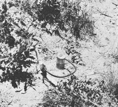
Fig. 6 - Close-up of geophone and the method of planting it. Interval taps are provided for proper spacing of pickups.
Fig. 7 - Recording and shooting truck showing cable reels in rear and instrument panel inside truck. Operators are shown studying the location record before moving their equipment to next point.
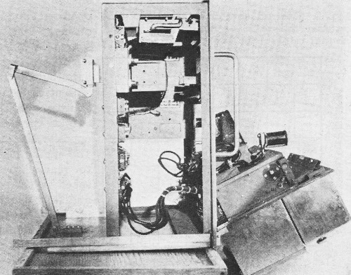
Fig. 8 - Side view of a geophysical recording camera which has been opened for inspection and servicing. This instrument is of the mirror galvanometer type and is widely used in oil location. The amplifiers generally have three or four stages of voltage amplification with bandpass filters to eliminate unwanted noises and interference. Dependent upon the type of amplifier in use, from 5 to 100 different frequency response curves may be selected by varying the upper and lower frequency limits. An automatic volume control keeps the output level approximately constant for input signal amplitude variations up to 1000 to 1. Maximum gain of these amplifiers is from 80 to 90 db. Such oddities as ants crawling over a geophone or wild game coming close can create enough signal intensity on the recording mechanism to render a record useless. Cars driving down a nearby highway, or in the case of an underwater job, a large school of fish or nearby motor boats, can accomplish this same ruinous effect on the records. From the amplifiers the signal is fed into the recording units of the camera, which may be one of two types; mirror galvanometer with moving coil deflection, or a string harp unit. The galvanometer, which is in general use in the modern equipment, has a natural frequency of 60 to 400 cycles and is nearly critically damped. The internal impedance ranges from 5 to 200 ohms and normal fun scale deflection in either direction may require from 5 to 40 millivolts. Each of the aforementioned types of signal indicating systems requires its own individual system of optics in order to transcribe the intelligence into a permanent record form. The mirror galvanometers have a tiny mirror suspended on the meter movement staff which swings with deflection of the coil. A light beam focused on this reflecting surface is directed through a converging prismatic lens, through a restricting horizontal slit, and onto the photographically sensitive paper which records the galvanometer's hor-izontal movements as the paper strip passes the slit vertically. An open view of such a camera is shown in Fig. 8, but constructional methods hide the more complex details referred to in this text. A squirrel cage rotor, used to print the timing lines on the photosensitive paper, is synchronously controlled with a tuning fork, therefore permitting the photo paper to record at an even rate of speed without detailing such work as highly accurate constant speed non-slip paper mechanisms. The string harp system prints shadow traces, white lines on a black background, while the mirror system produces black traces on white background. So in today's streamlined world of electronics, one of mankind's youngest achievements has found a permanent home in the petroleum industry. Radar, too, has found another peace-time application in the form of the Pathfinder marine navigation system, where water operations in the Gulf of Mexico are made safer and work can be started without being hindered by troublesome fog. Delays have proven costly in the past, and now with the aid of radar, operation costs are reduced. More rugged component parts allow portable swamp operations in native bayou flat boats, or rough terrain by back pack, and in all sorts of fields in the ton and a half trucks especially designed and built for this purpose. The greater percentage of the new oil reserves now accurately charted have been located by such methods, one more modern magic act for which we credit electronics and radio for top-notch assistance.
Posted April 5, 2023 |
|||||||||||||
 |
|||||||||||||
|
|||||||||||||


|
||||||||||||||||||||||||||||||||||||


