|
|||||||||||||
 |
|||||||||||||
Telemetry in Flight Testing |
|||||||||||||
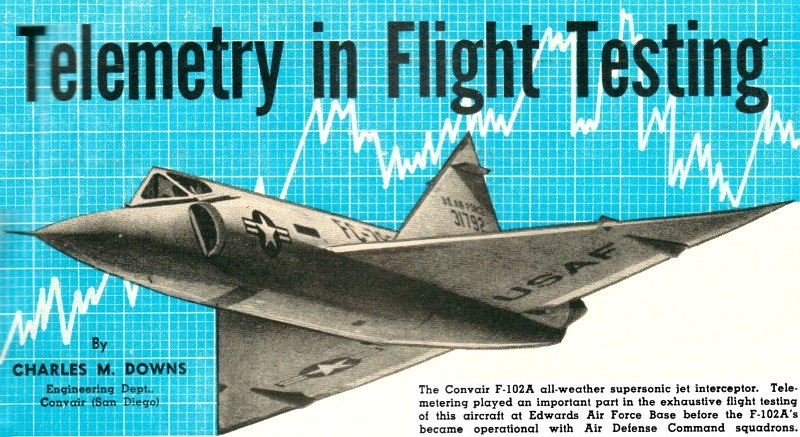
Telemetry in Flight Testing
The Convair F-102A all-weather supersonic jet interceptor. Telemetering played an important part in the exhaustive flight testing of this aircraft at Edwards Air Force Base before the F-102A's became operational with Air Defense Command squadrons. By Charles M. Downs Engineering Dept., Convair (San Diego) Part 1 of a two-part series on principles and applications of telemetering as used in developmental aircraft testing. The past few years a new application of electronics has "come of age." Telemetering (meaning to measure from a distance or to transmit a measurement) which has been used for the last ten years in missiles and rockets is now extensively used in flight testing military and commercial aircraft. With the advent of supersonic aircraft there was a need for a measuring system that would operate automatically with accuracy and precision without distracting the pilot of he aircraft in any way. Various airborne recording devices had the accuracy required but took up too much space, were too heavy, or were too restricted in the type of data they could record. As an example, one type of recording oscillograph used as an airborne recorder weighs 70 pounds, records 26 functions and has a frequency range of from d.c. to about 500 cycles. With additional equipment (linear amplifiers) the frequency range is extended to 3000 cycles. A telemetering system weighing half as much can record many more functions with a response on some subcarrier bands (see Table 1) of from d.c. to speech frequencies. Safety functions such as temperature, pressure, and acceleration can be instantly and continuously monitored on the ground during flight. If safe limits are exceeded, the pilot can be notified for corrective action. When an aircraft crashes into the ground at 500 miles per hour, there is little left from which to determine the cause of the crash. Lives have been saved because records, safe on the ground, revealed the cause of system or structural failure in telemetered aircraft. Data from airborne recorders would have been lost. Since recording oscillographs are an important part of the receiving station, it should be pointed out that telemetering has not replaced the oscillograph as a flight test recorder; it has only moved the oscillograph down on the ground where its full capabilities can be utilized. An oscillograph uses small mirrors mounted in galvanometer movements to reflect beams of light onto a moving strip of photosensitive paper. Thus the waveform of the current fed to the coil of the galvanometer is photographed as a continuous graph. Paper speed is variable from about 0.5 to 100 inches per second. One of the factors which limits the upper frequency response of an airborne oscillograph is paper speed. Due to the short supply of paper that can be carried aloft, the speed must be kept low if more than a few minutes of flight are to be recorded. This problem is overcome when the recorder is located in the ground station. Telemetered data stored on magnetic tape can be played back as many times as desired and oscillograph records may be made at any paper speed. Here it should be pointed out that oscillograph records are usually employed to determine which parts of the flight should be selected for further data reduction. Theory of Operation The theory of operation of an FM/PM telemetry system should be easily understood by anyone familiar with audio circuits. Several audio oscillators, operating at different frequencies, are frequency modulated by their associated pickups. The frequency-modulated audio signals are used to phase modulate a radio transmitter operating in the range of 215 to 235 megacycles. The r.f. signal is, in turn, picked up by a receiving station where the audio output of a receiver is passed through bandpass filters which separate the subcarrier oscillators (the audio oscillators in the aircraft) from the complex audio signal. The output of each bandpass filter is then fed into an audio discriminator which produces a varying d.c. voltage corresponding to the frequency shift of the subcarrier oscillator. The current in the discriminator output signal is the electrical equivalent of the original modulating signal obtained from the pickup in the aircraft. The discriminator output is then fed into electro-mechanical recorders such as recording oscillographs and pen recorders. Tape recorders, at the same time, record the audio output of the receivers so that in case of failure of one of the discriminators or electro-mechanical recorders, the data will not be lost. The tape playback can be fed directly into automatic data reduction computers if additional data reduction is required. Airborne Components
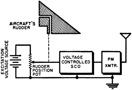
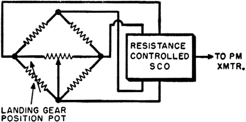
Table 1 - The various sub carrier bands that are employed in telemetering systems. Let us now consider various components of a system and their functions. Pickups and subcarrier oscillators (SCO's) fall into three basic types: voltage-, resistance-, and inductance-controlled. Of these three, the voltage-controlled oscillator is probably the most widely used. A diagram of a simple voltage-controlled system is shown in Fig. 1. Excitation voltage (in this case d.c.) is applied across a precision potentiometer. The shaft of the potentiometer is linked to an angular motion such as the rudder of an aircraft. The signal voltage from the arm of the pot is fed through shielded wire to the SCO. In one type of voltage-controlled SCO the input signal is fed to a reactance modulator combined with a Hartley oscillator. In another type, a free-running multivibrator is frequency modulated by using the signal voltage to bias the grid of one half of the oscillator. The frequency stability of either of these types under steady-state input conditions is excellent. The frequency deviation of a voltage-controlled SCO is an inverse function of signal polarity shift. In other words, when the signal is made more positive, the output frequency decreases. Two voltage ranges are generally used: 0 to 5 volts and ±2.5 volts. Since very sharp bandpass filters (down 60 db a few cycles past the bandpass limit) are used in the receiving station, SCO bandwidth limits and therefore input voltage limits must be carefully observed. Band limits (deviation limits) are determined as follows. There are 18 SCO frequencies established by the Department of Defense's Research and Development Board (RDB) now in use. (See Table 1.) Each SCO is allowed to deviate 7.5% of its center frequency each side of center frequency. As an example, given a 2.3 kc. SCO with a voltage range of 0 to 5 volts, the output frequency at 2.5 volts would be 2300 cps or ƒh. At 5 volts the frequency would be 2127 cps or ƒl. With 0 volt applied, the frequency would become 2473 cps or ƒh To provide a "fudge factor" and to reduce noise, many systems are operated at 80% bandwidth. Bandwidth now becomes 80% of 7.5% of ƒc. Special 15% units are available which are used when wide-band operation is desired. So far, we have considered only a d.c. modulating signal. Although a.c. can be used to modulate voltage-controlled oscillators, another factor must be considered: that of the highest a.c. frequency that can be applied. Naturally, it would be impossible to impress 2000-cycle modulation on a 2300- cycle SCO. Generally, it may be said that up to and including the 14.5 kc. band, maximum modulating frequency should not be more than 1.5% of ƒc. Above 14.5 kc., 3% is the maximum. These limits are conservative and can be exceeded but a point will be reached where severe intermodulation will occur. It should be remembered, however, that it is the instantaneous value of an a.c. modulating signal and not the frequency of the signal that causes the SCO to deviate. Voltage-controlled oscillators are used to measure control surface positions, gas and liquid pressures, vibration, acceleration, or any function which can be made to produce varying d.c. or a.c. voltage. A 70 kc. voltage-controlled SCO can be modulated by the pilot's microphone to provide one-way communication from the aircraft to ground. This can be used to record the pilot's comments which, for security reasons, cannot be transmitted over the aircraft's normal communications system. The second basic type of SCO is the resistance-controlled oscillator which changes frequency when a resistance change occurs in one or more arms of an a.c.-excited Wheatstone bridge. A basic resistance-controlled oscillator system is shown in Fig. 2. Bridge unbalance causes phase shift to occur in a phase-sensitive amplifier-oscillator loop. Sensitivity is determined by the number of active arms. Strain-sensitive bridges, precision potentiometers, and other variable resistance transducers are employed with resistance-controlled oscillators. A troublesome drawback is present in resistance-controlled systems. The shunt capacitance of the shield wire used between the pickup and oscillator causes the response curve of the oscillator to become slightly parabolic. (See Fig. 3.) This can be reduced, however, by shunting the bridge at the SCO with another capacitance to balance the unwanted capacitance of the shielded wire.
Fig. 1 - Block diagram of a simple voltage controlled subcarrier oscillator system.
Fig. 2 - Resistance controlled SCO system.
Fig. 3 - Resistance controlled SCO response. The third widely used type of SCO is the inductance-controlled oscillator. Mechanical motion is transferred to a Mumetal slug which is suspended in the field of a coil. The slug is oil- or air-damped, depending on the frequency response desired. The coil comprises the inductance of a Hartley LC oscillator. Thus the frequency of the oscillator is modulated by the mechanical motion. The pickup is not usually mounted more than a few feet from the oscillator because the shunt capacitance of the shielded wire can lower the frequency of the oscillator to a point where it is out of the particular band being used, or can actually prevent the SCO from oscillating. This is overcome by mounting the pickup near the oscillator and running tubing (in the case of a pressure measurement) from the oscillator-pickup location to the measurement point. In the case of an acceleration measurement, the accelerometer can be mounted with the oscillator at the point where acceleration is to be measured. Many special types of pickups are on the market which are designed to do a specific job such as the measurement of airspeed, altitude, fuel flow, and fuel quantity. Some of these contain their own SCO's while others convert hard-to-measure functions into easily handled voltage, inductance, or resistance changes. The Radio Transmitter After the audio output of the SCO's in a system (most systems use from ten to twelve SCO's) have been mixed through voltage dividers into a common audio bus, the combined or "complex audio" signal is applied to the modulator input of a crystal-controlled, phase-modulated transmitter. For those unfamiliar with the main difference between a phase-modulation and a frequency-modulation system, it might be well to point it out. The end result in either case is the same; the frequency of the transmitter becomes a function of the modulation impressed on that transmitter. However, that result is achieved by different methods. An FM transmitter is actually amplitude modulated. That is, the frequency change of the transmitter is a function of the amplitude of the modulating signal. A signal of 10,000 cps would cause the same frequency shift as a signal of 1000 cps if their amplitudes were equal. The rate at which the frequency of the transmitter is varying, however, is dependent on the frequency of the modulating signal that is used. In a phase-modulated transmitter, the amount of frequency deviation of the transmitter is a function of both amplitude and frequency of the modulating signal. Given a modulator with flat frequency response, and a ten SEO system with equal levels for all ten SEO's, the deviation of the transmitter caused by each SEO would be proportional to the frequency of the SEO. However, the frequency response of the modulator tube and circuit is far from flat. The modulator tends to attenuate the level of the higher frequency SEO's. The result of these two opposing response curves (the increasing deviation of the transmitter with an increase in modulation frequency, and the attenuation of the higher frequency seo's by the modulator tube) is a decrease in deviation response with an increase in frequency. It is therefore necessary to pre-emphasize the higher frequency SEO's in order to obtain the correct modulation index for a given transmitter. The transmitter is a compact frequency multiplier with about 2.5 watts output. When used to telemeter vehicles or objects which are fairly close to the receiving station (1 to 3 miles) the power output of the transmitter alone is enough to deliver satisfactory strength; but when used in missiles and aircraft, additional power amplifiers are required. Telemetering power amplifiers usually contain 1 or 2 tubes (4X150A and832B are commonly used types) and produce from t15 to 100 watts output, depending on tube type and plate supply voltage. Antenna Systems Antenna systems are more of a problem than usual when mounted on supersonic aircraft. In addition to exhibiting a satisfactory radiation pattern, the antenna must produce a minimum of drag and turbulence. For this reason flush antennas such as notch exciters, slot antennas, and quarter-wave dipoles imbedded in non-metallic material are used extensively. The air-speed measuring system on flight test aircraft usually consists of a short tapered tube, an inch or two in diameter, extending from the center of the nose of the aircraft. If insulated, the airspeed boom can serve as a quarter wave "spike" antenna. Blade antennas, in the form of an airfoil, can be mounted on the bottom of the aircraft where maximum r.f. propagation is effected. A quarter wavelength at the frequencies in use is about 9 to 11 inches which facilitates compact antenna design. One system uses one antenna mounted in each wingtip to prevent signal dropout during rolls and sharp banks. Duplexers are in use which permit two transmitters of different frequencies to be loaded into a single antenna; three duplexers may be used to load four transmitters into one antenna system. Design Considerations
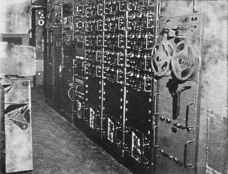
Convair's receiving station at Edwards AFB flight test facility. In right foreground is playback unit for airborne tape. The next three racks contain sub-carrier discriminators. Left racks contain receivers, test gear, and patch boards. Telemetering systems are manufactured in "building block" form. Due to the individual requirements of any one flight research program, it would be hard to build a "package deal" to be installed in all types of aircraft. Therefore, it is up to the engineers and technicians working with the equipment to use their ingenuity in selecting the components for their system. With these things in mind, a few design considerations will be discussed here. Every system has its drawbacks and telemetry is no exception. Possibly the greatest problem encountered in a measurement system is noise. Types of noise existent in a telemetering system can be placed in two general classes: intermodulation and random or transient noise. Intermodulation can be caused by applying a complex wave to a non-linear impedance. Appearing as beats between the component frequencies of the complex signal, it produces frequencies which are not present in the original complex wave. Beat frequencies are always present in a complex audio bus (the combined output of the several subcarriers in a telemetering system) but the levels of the beats are down 30 db or so in relation to subcarriers. If two subcarrier levels are allowed to increase to a high enough level, the beat between them will attain a high enough level to seriously affect the other subcarriers in the system. Intermodulation can be reduced or eliminated by the use of impedance matching devices, extra insulation, and carefully balanced subcarrier levels. Random and transient noise should, if possible, be eliminated at its source. Relays switching reactive loads can produce a transient which can be picked up fifty feet away. A large capacitor or neon lamp placed across the contacts of hte relay can suppress much of the noise. Ground loops can be avoided by grounding the shielding at one point only and as close to the SCO as possible. Noise which amplitude modulates the SCO envelope is reduced by the limiters in the receiving station radio receivers. However, noise which frequency modulates the SCO must be eliminated at its source if the frequency response of the SCO is to be utilized. In the case of a d.c. or low-frequency a.c. measurement, the recording device can be damped so that its upper frequency limit falls below the noise frequency. Low-pass filters in the discriminator output circuit are also useful in noise reduction but again the high-frequency response of the subcarrier is limited.
(Concluded next month)
Posted December 23, 2022 |
|||||||||||||
 |
|||||||||||||
|
|||||||||||||


|
||||||||||||||||||||||||||||||||||||


