|
|||||||||||||
 |
|||||||||||||
Transmission Lines |
|||||||||||||
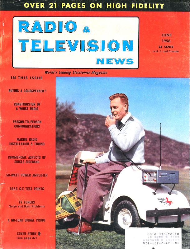
Lots of RF transmission cable parameter charts are available on the Internet, but what sets this one apart is that is has entries for some of the popular 300 Ω twin-lead cables of the rooftop television antenna era. It appeared in a 1956 issue of Radio & Television News magazine. Mentioned in the article is the reason most TV lead-in cable was colored brown was to help keep the sun's ultraviolet rays from penetrating and deteriorating the plastic. Author Robert Gary claims silver coloring was also used to reflect the UV, but I don't recall ever seeing silver twin-lead - maybe it was a regional thing like for in the southwest. At the time, μμfd (micro-microfarad) was commonly used rather than pF (picofarad). He also mentions the G-Line transmission cable used by many of the Community TV providers. See "The G-Line Antenna Lead-In, by Leonard Lieberman, and "The "G-Line" Community TV System," by Robert Gary for more info." Transmission Lines By Robert B. Gary
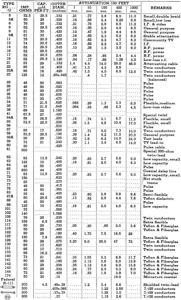
This table will help you select the right wire or cable for test leads, transmission lines, and other uses. Whether a short piece of coaxial cable is needed as a shielded test lead for an oscilloscope, or 10 miles of transmission line is to be selected for a community TV system, the electrical characteristics of the various commercially available cables are important criteria. The table presented here lists all of the most frequently-used coaxial cables and TV twin-leads and gives their electrical characteristics. The wires and cables in the table are listed by "RG" numbers since these represent the only standard designations available for a great variety of manufacturer type numbers. Some of the types are variations of a standard type; for example, one variation may have a special outer insulation effective at low temperatures, or a metal outer sleeve or "armor." In many instances the letter "A" or "E" follows the type number and indicates that either a different type outer jacket or some other minor variation exists. The type numbers listed represent the basic, up-to-date cables manufactured by most of the major cable suppliers. Note that the characteristic impedances do not always fall into the standard 50 or 75 ohms expected from most diagrams. In general, such values as 48 or 53 ohms are close enough to 50 ohms to be considered such. The outer diameter of a cable is important because it will determine such mechanical details as cable clamps, connector types, and feedthrough holes. The electrical data includes the effective capacity in micromicrofarads per foot, an important consideration in cables feeding either pulse networks or tuned circuits. The cable for an oscilloscope probe, for example, should have minimum capacity. If the nominal scope input capacity is 30 μμfd. without the cable and a 6-foot length of RG 58/U is added, this in-creases the effective input capacity to more than 200 μμfd., which may be sufficient to distort the leading edge of a short duration pulse. Attenuation per 100 feet is stated in decibels for the most important frequencies. While attenuation in transmission lines becomes critical usually only in long distance systems such as in community TV installations, even shorter lengths require some consideration. Consider the lead-in from a 30-foot tower-mounted antenna array to a receiver located another 120 feet from the tower. For the low-band v.h.f. stations the attenuation with flat twin-lead (300-ohm) for the entire length would be less than 2 db nominally. If a u.h.f. station near 500 mc. were received on this installation the line loss alone would be over 4.5 db, Use of shielded twin-lead would double the attenuation. Some of the latest coaxial cable types use Teflon and Fiberglas insulation. Extremely high temperature performance is the major advantage of these types and their greater cost dictates their use mostly in aircraft and missile systems. New miniature coaxial cable is also most frequently found in specialized government equipment. Polyethylene has become the standard insulating material used in TV lead-ins. This plastic is quite tough and moisture resistant. Unfortunately it deteriorates rapidly under the ultraviolet rays from the sun. To overcome this drawback, most 300-ohm cable is pigmented with a brown material which keeps the ultraviolet rays out. Recently, some suppliers have come out with a silver-colored twin-lead which has even better resistance to the sun due to the reflective qualities of the silver-type pigmentation. Clear plastic twin-lead should never be used on exterior installations, but will perform satisfactorily where the sun cannot get at it. In addition to the cables listed, most of the suppliers for community TV systems offer special varieties, usually double shielded. One community TV system uses "G" line, which consists only of an inner conductor and dielectric without an outer shield. The theory behind the operation of this type of transmission line was explained in the article, "The G-Line Antenna Lead-in," in the April, 1955, issue of Radio & Television News. Another type of lead-in that is quite popular where long transmission line lengths is the rule is open or "ladder" line, which consists of two solid conductors separated by small bars of solid polyethylene. |
|||||||||||||
 |
|||||||||||||
|
|||||||||||||

|
||||||||||||||||||||||||||||||||||||