|
|||||||||||||
 |
|||||||||||||
Are Your Electrolytics Leaky? |
|||||||||||||
Anyone who has dealt with older electronics equipment knows that one of the first kinds of components to go bad is the electrolytic capacitor. Materials used at the time degraded fairly rapidly, especially compared to modern materials, which facilitated leakage of stored charge between the rolled up layers of conductive plates and interstitial insulating paper (or other material) layers. As outlined in this 1957 article from Radio & Television News magazine, symptoms of electrolytic capacitor malfunction in radio and television are most often some form of audible noise, light or dark lines within the picture scan, or outright power supply failure. Since electrolytics are typically large valued capacitors, they are used in power supply circuits for filtering the line 50 or 60 Hz (depending on your country) AC frequency (and their harmonics) and for interstage AC coupling. This article presents a simple method for testing leakage levels in electrolytic capacitors to determine whether they should be replaced. Many restorers of old electronic equipment routinely replace all the original electrolytic capacitors because it is almost certain that leakage will either immediately or in short order cause problems. Are Your Electrolytics Leaky? 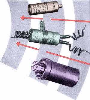 By Ben Crisses and David Gnesin By Ben Crisses and David Gnesin
It is not unusual for a service technician to accumulate quantities of electrolytic capacitors of questionable quality. The collection occurs in this way: In routine servicing, he may decide that the quickest way to check electrolytics is to bridge a doubtful unit with a new one. Even when results are indefinite, technicians will often wire the new unit in as a permanent replacement, as the proverbial "ounce of prevention." The old unit is laid aside without further examination, for time is important and customers are impatient. When business slows down, why not dig out these removed units and give them a qualitative check? It's easy. Since excessive leakage is the characteristic that impairs the efficiency of electrolytics, a measure of leakage current is the best test. If this leakage current is within the tolerance recommended by the manufacturer, the capacitor may be considered good. In fact, the production test and the tolerances generally used may be duplicated in the shop without much difficulty. A multimeter, a voltmeter, and a d.c. source (an old receiver will do for the latter) are the principal ingredients. In addition a 1-megohm potentiometer, a 10,000-ohm potentiometer, and a single-pole, single-throw switch are used. A fuse may also be added, as shown.
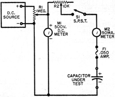
Fig. 1 - Leakage current through capacitor is measured at rated voltage with the simple test circuit depicted here.
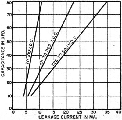
Fig. 2 - Leakage for a given combination of capacitance and voltage rating should not exceed values shown here. Fig. 1 shows the manner in which the meters, pots, switch, and d.c. source are connected, as well as the capacitor under test. Be sure, in this arrangement, that the capacitor is connected in the proper polarity, with its positive terminal going to the positive side of the voltage source. Begin the test with the switch open, by adjusting R1 so that the voltage being supplied for test purposes and being monitored by the voltmeter, is equal to the voltage rating of the capacitor. Then adjust R2 to the position of maximum resistance; that is, so that its full 10,000 ohms is in series with the capacitor and the milliammeter. Now the switch is closed and resistor R2 is moved toward its position of minimum resistance. This must be done slowly to avoid injury to the meter. Observe the reading on the milliammeter while rotating R2, comparing it with the graph of readings in Fig. 2. If the meter reading does not exceed the recommended maximum shown in this graph, the capacitor is within tolerance and has useful life ahead of it. An example will serve to illustrate: Suppose you have a 40-μfd. electrolytic rated at 450 volts. Hooking it up as shown in Fig. 1, R1 is set to supply 450 volts. After R2 is set to be fully in the circuit, S1, is closed. Now slowly begin reducing the resistance of R2 while observing the meter. If R2 can be completely shorted out without leakage current exceeding 19 milliamperes, the capacitor is still useful. An easily set up quality test for the many unused filter capacitors gathering dust in most shops. The ethics of impressing a used component into service as a replacement for a customer is something else again. There is no intention of encouraging the use of such parts instead of new ones. However, there are countless other applications around the shop where electrolytics in good condition, although they have already seen service, come in handy. One precaution should be observed: if, while decreasing R2, the milliammeter reading should begin to rise above 35 milliamperes, open S1 quickly. Leakage of this order indicates an extremely leaky capacitor, which could short out and damage the circuit.
Posted June 15, 2022 |
|||||||||||||
 |
|||||||||||||
|
|||||||||||||


|
||||||||||||||||||||||||||||||||||||


