 RF Cafe visitor L. Joseph wrote to
request that the following question be posted in hope that someone will provide
an answer. If you care to reply, please either
e-mail your answer to me so I can post it, or maybe reply on LinkedIn.
See answers below:
"This is the question I am trying to get an answer for:
Let us take a 100 ohm termination in a 50 ohm system and add a 50 ohm
transmission line of 0.2 lambda (0.2λ) length.
At the end of this 0.2 lambda line I will get an impedance corresponding
to some VSWR1.
Then, I change the termination from 100 ohms to 75 ohms and at the
end of the 0.2 lambda line VSWR2 will be VSWR2 =
VSWR1 / (100 / 75) = VSWR1 / 1.33
Will the same rule apply if the 0.2 lambda line impedance is not 50 ohms...
say 25 ohms?
Is there an easy way to make calculations in situations like this?"
Thanks to the folks who took the time to provide an answer

Greg F.
September 4, 2013
Dear L. Joseph and RF Café readers,
In regards to your Transmission Line Impedance question. The length of the transmission
line can be largely ignored here. A theoretical lossless transmission line will
only rotate the terminating impedance around on the same VSWR circle. You would
only need to take the transmission line length into account if it were long enough
for its attenuation characteristics to become significant.
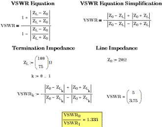
The direct answer to your question is yes, for (your) two termination impedances
the VSWR ratio will always be 1.33 regardless of the transmission line impedance.
As long as the transmission line impedance stays lower than your lowest termination
impedance.
I used Mathcad for the equations, but you should be able to make spread sheet
calculation to do the job. You'll find it interesting to play with the line impedance.
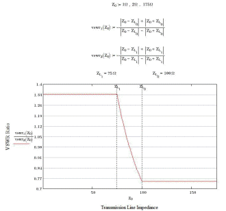
It will cause the VSWR ratio to change when it is between the two termination impedances.
 Added on September 5, 2013
I hope my solution helped, it was a fun distractions from work. I continued to
play with it after I sent my email. I found it very interesting that the VSWR ratio
became dynamic when the Line Impedance was between the two Termination Impedance.
As you know, for all practical purposes, transmission line impedance is fixed so
I've never spent any time exploring the effect of varying that parameter. I decided
to plot the VSWR Ration as a function of Line Impedance. You can post this as well
if you think it will be of interest.
L. Joseph responds:
September 5, 2013
"Thanks for the detailed answer!"
Posted September 3, 2013
|


