Stacked 9- & 17-Element Yagi TV Antenna Project Dave Jones, N1UAV Kirt's Cogitations™ #314
"Factoids," "Kirt's Cogitations," and
"Tech Topics Smorgasbord"
are all manifestations of my ranting on various subjects relevant (usually) to the
overall RF Cafe theme. All may be accessed on these pages:
RF
Cafe visitor Bob D. suggests if you have a hard time locating 300 Ω
twin lead cable that you consider buying one of the readily available
300 Ω FM dipole antennas and using its cable. Be sure
to protect it from UV exposure.
Every once in a while an RF Cafe visitor writes to let me know that he or she
found one of the vintage electronics magazine articles I post regularly useful.
It helps to validate my efforts, which is critical for motivation to continue. A
couple days ago Mr. Dave Jones (N1UAV), sent me a note about the stacked television
antenna project he undertook after finding the "How to Stack TV Antennas to Increase Signal Strength and to Reduce
Ghosts" article from the November 1965 issue of Popular Electronics
magazine. His location about 90 miles outside of Nashville, Tennessee, is a challenge
for trying to receive a good signal from a television station from both an attenuation
and multipath signal degradation perspective. Dave began with a single antenna,
but was not happy with the performance. The results of adding the second antenna
is amazing. Dave's letters and photos are posted below. His accomplishments on this
and many other technical endeavors are quite impressive. BTW, you can see from the
letter why Dave selected the Ham call sign that he did.
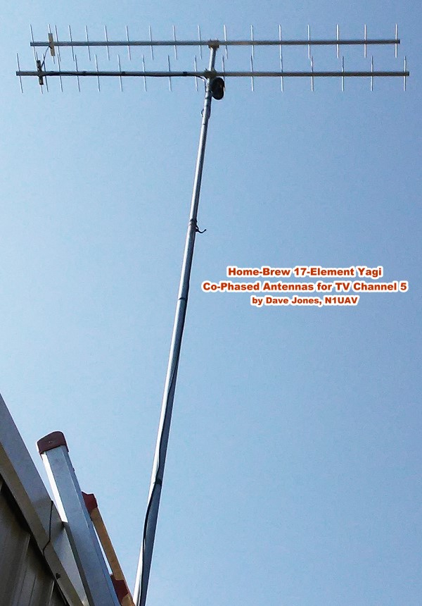
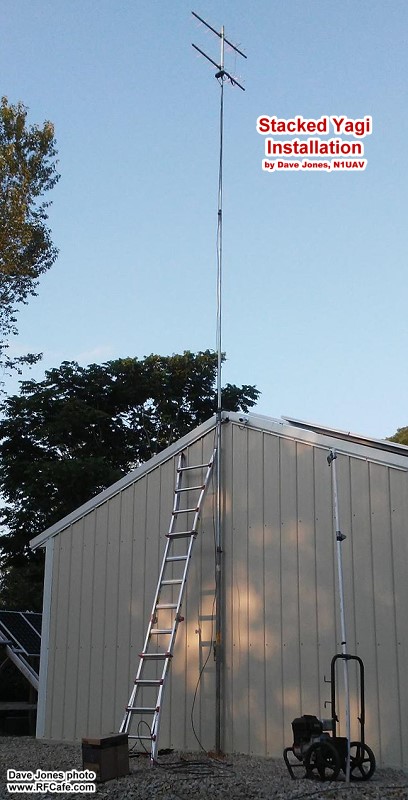
17-element stacked Yagi antenna array
Dave Jones, N1UAV
September 7, 2019 Update
Dave wrote again with some photos and details of his new stacked 17-element Yagi
antenna array. See his video below.
"My objective was to receive WTVF channel 5 Nashville, TN. I wanted an outside
TV antenna as a back up to our DirecTV satellite system for local news during rain
induced drop outs."
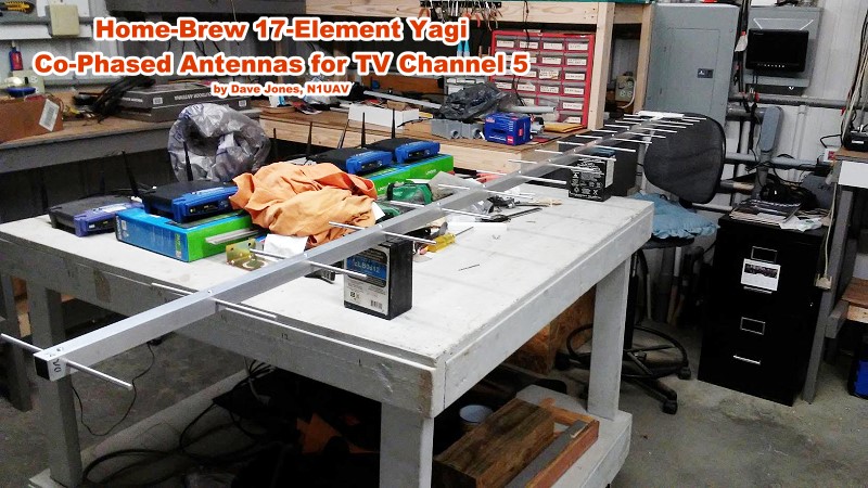
To build the 17 element Yagis I used an 8 foot link of 1" x 1" square aluminum
tubing and about 11 feet of 1/4 inch solid round aluminum rods. I bought the rods
in 10-foot links and cut them to the lengths specified by the
Yagi Antenna Calculator. I used an 8 foot link of 1" x 1" aluminum
angle as a drill template to make it easier to make a 2nd identical antenna to the
first one, this way I only had to layout the spacing for the elements once and then
transfer the locations to each of the two square aluminum tubes. I used a 1" x 5"
piece of
King StarBoard for the dipole mounting block to attach the mounting
blocks to the square aluminum tubes. I used #6 x 1" galvanized (zinc-plated) screws.
To attach the dipoles to the dipole mounting block I used 1/4 inch coaxial cable
clamps.
- 2 each -- Steelworks 1" x 1" x 96" aluminum plain square tube,
11392.
- 1 each -- Steelworks 1" x 1" x 96" aluminum solid angle,
11354.
- I bought the solid 1/4 inch aluminum rod from a metal supply in town it was
$5.00 for a 10 foot stick. Your price may vary, I used 11.5 feet per antenna, or
around 1-1/4 sticks for each antenna (Lowe's 1/4" x 36",
11270).
Homebuilt 17-element Yagi antenna
Dave Jones, N1UAV
Fasteners: All of the screws, wing nuts and washers used for the electrical
connections are stainless steel.
- The phasing harness was made from 19.5 inches of 300 ohm twin lead. 300 ohm
twin lead can be found on
ebay.com or
amazon.com
-
RG6 F-type connectors I had left over from my satellite days.
Note: * Only use good connectors DO NOT USE TWIST ON connectors*.
Dave Jones, N1UAV, Builds a 17-Element Yagi Antenna
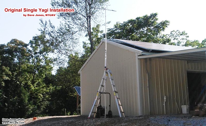
Original single-Yagi installation.
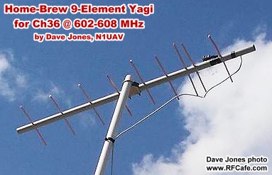
9-element Yagi close-up.
Stacked 9-element Yagi antennas.
Close-up of stacked Yagi antennas.
July 27, 2019
Kirt:
"My name is Dave Jones. I am an RC modeler, electronics guy and all around tinker.
You can see my web at www.auav.net.
I am retired and not in the UAV business anymore I keep the website running
for reference. I now live in Tennessee about 90 miles east of Nashville and I
have been wanting to put up a TV antenna to receive Channel 5 out of Nashville.
I was in the Satellite TV business back in the 80's (the big C band
dishes) and I installed a lot of TV antennas to go with the satellite
dishes. Back then you could buy a custom made Yagi TV antenna cut for
any RF channel that you wanted, but not today. I called Winegard and Channel
master and was told that they don't make custom antennas anymore. So I thought
I would try building one using 3/4 inch PVC pipe and 1/4 inch copper tubing. I search
on line and found an on line Yagi Uda Antenna Calculator. "
"I used the Calculator to determine the boom and elements lengths and spacing.
I used 605 MHz for my antenna because Ch 5 in Nashville now transmits on
UHF Ch 25 and are scheduled the change to Ch 36 (605 MHz) in September or October of
this year. This week I built a 605 MHz 9 element Yagi and mount it on a temporary
mount about 15 ft above ground level and it worked perfectly, unfortunately we
had a cold front come though while I was testing it and after the cold front dissipated
so did the signal. I mounted a 40 ft push up mast to the side of my workshop
and installed the antenna with a pre-amp and could not receive Ch 5. What
was driving me nuts was Ch 17 the
Fox channel out of Nashville was coming in fine. It has the same transmitting
power (1 MW) and is located 2 miles farther away from us than Ch 5, and
its tower height is a couple of hundred feet lower than Ch 5's tower. The only
other thing is Ch 17's frequency - even thought it is Ch 17 they
transmit on Ch 15 and Ch 5 transmits on Ch 25 (leave it to the
government to make things crazy). "
"I wanted to add a 2nd antenna but could not find any of the old flat 300
ohm twin lead like we use to use back in the dark ages. I check with
a couple of TV shops and went to Lowes and no one had any, then I remembered
that my father in-law had some old TV antenna parts in his old garage
so I went down and found about 20 ft. I only needed 2 ft.
"
"I then searched Google on how to co-phase two TV antennas and found the
November 1965 Popular Electronics article on stacking antennas, on your
RF Cafe website. It gave the correct spacing for the antennas and the length of
the phasing harness the article said make the harness one full wave length of the
lowest frequency that you are trying to receive. In my case I was targeting Ch 5
that is now on Ch 25 but will soon be moved to Ch 36, so I made my harness
for Ch 36, or 605 MHz. That worked out to be 19.5 inches. I did not expect
it to work but I built a 2nd antenna anyway and mounted it under the first
one, connected it with the phasing harness, and pointed it toward Nashville. I went
in and checked the TV and found I had a picture. I checked the signal strength and
it had gone from nothing to good and the picture is locked in solid*."
* A digital TV broadcast signal, unlike
an analog signal, is either there or it's not - nothing in-between. A digital signal
at the edge or reception will break up into a pixelated display rather than just
increasing in "noise" like in the olden days. - Kirt B.
Also, I have found 300-ohm twin lead on eBay and sometimes it shows up on Craigslist
(usually at a pretty good price).
According to the Path Loss calculator in my
Espresso Engineering Workbook™ (at right), the signal attenuation
over 90 miles at 608 MHz is about 131 dB. For the 1 MW transmitter
(assuming zero antenna gain since TV broadcast antennas are typically omnidirectional
in azimuth), that works out to about -41 dBm of power at Dave's location, not
accounting for obstructions and/or multipath.
After requesting to Dave that he permit me to post his info, he followed up with
this:
July 31, 2019
Kirt:
I just found your YouTube Channel and watched the video "Alliance Tenna
Rotor Model U 100 4 8 2018." I don't know how many of those I installed
back in the Dark Ages; you could not kill one.
- Dave Jones, N1UAV
July 31, 2019
Kirt:
Thanks for the reply, sure go ahead post the story and photos. "It will also
serve the purpose of demonstrating how even half a century old articles can still
be useful." I tell people RF is RF and antennas don't know if it's a digital or
analog signal. This was a proof of concept prototype done on the cheap using what
I had laying around, I am going to build two new antennas using 1X1 square aluminum
tubing and 4 more elements each to get 3 more dB of gain from of each of the antennas.
I have one station that's fading out during the day but is good at night. That should
be a total of 6 dB over what I have now and I think that should resolve the
daytime fading.
One of the 9 element prototype antennas has a gain of around 11.24 dBd**,
by co-phasing the two I should have gotten around 14.24 dBd. If I increase
the gain of one antenna to 14.24 dBd by adding more 4 more elements and then
co-phasing two of them together, I should have around 17.24 dBd. I know the
beam width will get narrower as the gain goes up but I think it should be ok. I
will send you build photos and a list of parts that I use for my new antennas so
you can do a follow up.
If you have the time please check out my YouTube channel, it's called "On My
Workbench." It's on some of the projects that I have done over the years. I
will be posting the Prototype and the new antennas to "On My Workbench." Thanks.
- Dave Jones, N1UAV
** dBd is decibels relative to the gain of a dipole antenna, which
is 2.15 dBi; therefore, 0 dBd = 2.15 dBi.
RF Cafe began life in 1996 as "RF Tools" in an AOL screen name web space totaling
2 MB. Its primary purpose was to provide me with ready access to commonly needed
formulas and reference material while performing my work as an RF system and circuit
design engineer. The World Wide Web (Internet) was largely an unknown entity at
the time and bandwidth was a scarce commodity. Dial-up modems blazed along at 14.4 kbps
while tying up your telephone line, and a lady's voice announced "You've Got Mail"
when a new message arrived...
Copyright 1996 - 2026
All trademarks, copyrights, patents, and other rights of ownership to images
and text used on the RF Cafe website are hereby acknowledged.


 "
"