NEETS Module 5 - Introduction to Generators and Motors
Pages i,
1-1,
1-11,
1-21,
1-31,
2-1,
2-11,
3-1,
3-11,
4-1,
4-11, Index
Chapter 2 Direct CURRENT MOTORS
Learning Objectives Upon completion of this chapter you will be able to: 1. State the factors that determine the
direction of rotation in a DC motor. 2. State the right-hand rule for motors.
3. Describe the main differences and similarities between a DC generator and a DC motor.
4. Describe the cause and effect of counter EMF in a DC motor. 5. Explain the term "load" as it
pertains to an electric motor. 6. List the advantages and disadvantages of the different types of DC
motors. 7. Compare the types of armatures and uses for each.
8. Discuss the means of controlling the speed and direction of a DC motor. 9. Describe the effect of
armature reaction in a DC motor. 10. Explain the need for a starting resistor in a DC motor. Introduction The DC motor is a mechanical workhorse, that can be used in many different ways. Many large pieces of
equipment depend on a DC motor for their power to move. The speed and direction of rotation of a DC motor are
easily controlled. This makes it especially useful for operating equipment, such as winches, cranes, and missile
launchers, which must move in different directions and at varying speeds. Principles of Operation The operation of a DC motor is based on the following principle: A current-carrying conductor placed
in a magnetic field, perpendicular to the lines of flux, tends to move in a direction perpendicular to the
magnetic lines of flux. There is a definite relationship between the direction of the magnetic field, the
direction of current in the conductor, and the direction in which the conductor tends to move. This relationship
is best explained by using the RIGHT-Hand RULE for MOTORS (fig. 2-1). 2-1
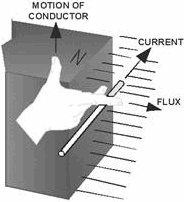
Figure 2-1. - Right-hand rule for motors. To find the direction of motion of a conductor, extend the thumb, forefinger, and middle finger of your
right hand so they are at right angles to each other. If the forefinger is pointed in the direction of magnetic
flux (north to south) and the middle finger is pointed in the direction of current flow in the conductor, the
thumb will point in the direction the conductor will move. Stated very simply, a DC motor rotates as a
result of two magnetic fields interacting with each other. The armature of a DC motor acts like an electromagnet
when current flows through its coils. Since the armature is located within the magnetic field of the field poles,
these two magnetic fields interact. Like magnetic poles repel each other, and unlike magnetic poles attract each
other. As in the DC generator, the DC motor has field poles that are stationary and an armature that turns on
bearings in the space between the field poles. The armature of a DC motor has windings on it just like the
armature of a DC generator. These windings are also connected to commutator segments. a DC motor consists of the
same components as a DC generator. In fact, most DC generators can be made to act as motors, and vice versa.
Look at the simple DC motor shown in figure 2-2. It has two field poles, one a north pole and one a south pole.
The magnetic lines of force extend across the opening between the poles from north to south.

Figure 2-2. - Dc motor armature rotation. The armature in this simple DC motor is a single loop of wire, just as in the simple armature you studied
at the beginning of the chapter on DC generators. The loop of wire in the DC motor, however, has 2-2
current flowing through it from an external source. This current causes a magnetic field to be
produced. This field is indicated by the dotted line through the loops. The loop (armature) field is both
attracted and repelled by the field from the field poles. Since the current through the loop goes around in the
direction of the arrows, the north pole of the armature is at the upper left, and the south pole of the armature
is at the lower right, as shown in figure 2-2, (view A). Of course, as the loop (armature) turns, these magnetic
poles turn with it. Now, as shown in the illustrations, the north armature pole is repelled from the north field
pole and attracted to the right by the south field pole. Likewise, the south armature pole is repelled from the
south field pole and is attracted to the left by the north field pole. This action causes the armature to turn in
a clockwise direction, as shown in figure 2-2 (view B). After the loop has turned far enough so that its
north pole is exactly opposite the south field pole, the brushes advance to the next segments. This changes the
direction of current flow through the armature loop. Also, it changes the polarity of the armature field, as shown
in figure 2-2 (view C). The magnetic fields again repel and attract each other, and the armature continues to
turn. In this simple motor, the momentum of the rotating armature carries the armature past the position
where the unlike poles are exactly lined up. However, if these fields are exactly lined up when the armature
current is turned on, there is no momentum to start the armature moving. In this case, the motor would not rotate.
It would be necessary to give a motor like this a spin to start it. This disadvantage does not exist when there
are more turns on the armature, because there is more than one armature field. No two armature fields could be
exactly aligned with the field from the field poles at the same time. Q1. What factors determine the
direction of rotation in a DC motor?
Q2. The right-hand rule for motors is used to find the relationship between what motor characteristics?
Q3. What are the differences between the components of a DC generator and a DC motor? COUNTER EMF While a DC motor is running, it acts somewhat like a DC generator. There is a magnetic field from the field
poles, and a loop of wire is turning and cutting this magnetic field. For the moment, disregard the fact that
there is current flowing through the loop of wire from the battery. As the loop sides cut the magnetic field, a
voltage is induced in them, the same as it was in the loop sides of the DC generator. This induced voltage causes
current to flow in the loop. Now, consider the relative direction between this current and the current
that causes the motor to run. First, check the direction the current flows as a result of the generator action
taking place (view a of fig. 2-2). (Apply the left-hand rule for generators which was discussed in the last
chapter.) Using the left hand, hold it so that the forefinger points in the direction of the magnetic field (north
to south) and the thumb points in the direction that the black side of the armature moves (up). Your middle finger
then points out of the paper (toward you), showing the direction of current flow caused by the generator action in
the black half of the armature. This is in the direction opposite to that of the battery current. Since this
generator-action voltage is opposite that of the battery, it is called "counter EMF." (The letters EMF stand for
electromotive force, which is another name for voltage.) The two currents are flowing in opposite directions. This
proves that the battery voltage and the counter EMF are opposite in polarity. At the beginning of this
discussion, we disregarded armature current while explaining how counter EMF was generated. Then, we showed that
normal armature current flowed opposite to the current created by the counter EMF. We talked about two opposite
currents that flow at the same time. However, this is a 2-3
bit oversimplified, as you may already suspect. Actually, only one current flows. Because the counter EMF can
never become as large as the applied voltage, and because they are of opposite polarity as we have seen, the
counter EMF effectively cancels part of the armature voltage. The single current that flows is armature current,
but it is greatly reduced because of the counter EMF. In a DC motor, there is always a counter EMF
developed. This counter EMF cannot be equal to or greater than the applied battery voltage; if it were, the motor
would not run. The counter EMF is always a little less. However, the counter EMF opposes the applied voltage
enough to keep the armature current from the battery to a fairly low value. If there were no such thing as counter
emf, much more current would flow through the armature, and the motor would run much faster. However, there is no
way to avoid the counter EMF.
Q4. What causes counter EMF in a DC motor? Q5. What motor characteristic is affected by counter EMF? MOTOR Loads Motors are used to turn mechanical devices, such as water pumps, grinding wheels, fan blades, and circular
saws. For example, when a motor is turning a water pump, the water pump is the load. The water pump is the
mechanical device that the motor must move. This is the definition of a motor load. As with electrical
loads, the mechanical load connected to a DC motor affects many electrical quantities. Such things as the power
drawn from the line, amount of current, speed, efficiency, etc., are all partially controlled by the size of the
load. The physical and electrical characteristics of the motor must be matched to the requirements of the load if
the work is to be done without the possibility of damage to either the load or the motor. Q6. What is
the load on a DC motor?
PRACTICAL DC MOTORS As you have seen, DC motors are electrically identical to DC generators. In fact, the same DC machine may be
driven mechanically to generate a voltage, or it may be driven electrically to move a mechanical load. While this
is not normally done, it does point out the similarities between the two machines. These similarities will be used
in the remainder of this chapter to introduce you to practical DC motors. You will immediately recognize series,
shunt, and compound types of motors as being directly related to their generator counterparts.
Series DC MOTOR In a series DC motor, the field is connected in series with the armature. The
field is wound with a few turns of large wire, because it must carry full armature current. The circuit for a
series DC motor is shown in figure 2-3. 2-4
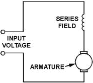
Figure 2-3. - Series-wound DC motor. This type of motor develops a very large amount of turning force, called torque, from a standstill.
Because of this characteristic, the series DC motor can be used to operate small electric appliances, portable
electric tools, cranes, winches, hoists, and the like. Another characteristic is that the speed varies
widely between no-load and full-load. Series motors cannot be used where a relatively constant speed is required
under conditions of varying load. A major disadvantage of the series motor is related to the speed
characteristic mentioned in the last paragraph. The speed of a series motor with no load connected to it increases
to the point where the motor may become damaged. Usually, either the bearings are damaged or the windings fly out
of the slots in the armature. There is a danger to both equipment and personnel. Some load must ALWAYS be
connected to a series motor before you turn it on. This precaution is primarily for large motors. Small motors,
such as those used in electric hand drills, have enough internal friction to load themselves. A final
advantage of series motors is that they can be operated by using either an AC or DC power source. This will be
covered in the chapter on AC motors.
Q7. What is the main disadvantage of a series motor? Q8. What is the main advantage of a series motor?
Shunt MOTOR A shunt motor is connected in the same way as a shunt generator. The field windings
are connected in parallel (shunt) with the armature windings. The circuit for a shunt motor is shown in figure
2-4. 2-5
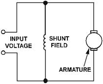
Figure 2-4. - Shunt-wound DC motor. Once you adjust the speed of a DC shunt motor, the speed remains relatively constant even under changing
load conditions. One reason for this is that the field flux remains constant. a constant voltage across the field
makes the field independent of variations in the armature circuit. If the load on the motor is increased,
the motor tends to slow down. When this happens, the counter EMF generated in the armature decreases. This causes
a corresponding decrease in the opposition to battery current flow through the armature. Armature current
increases, causing the motor to speed up. The conditions that established the original speed are reestablished,
and the original speed is maintained.
Conversely, if the motor load is decreased, the motor tends to increase speed; counter EMF increases, armature
current decreases, and the speed decreases. In each case, all of this happens so rapidly that any actual
change in speed is slight. There is instantaneous tendency to change rather than a large fluctuation in speed.
Q9. What advantage does a shunt motor have over a series motor? COMPOUND MOTOR
a compound motor has two field windings, as shown in figure 2-5. One is a shunt field connected in parallel with
the armature; the other is a series field that is connected in series with the armature. The shunt field gives
this type of motor the constant speed advantage of a regular shunt motor. The series field gives it the advantage
of being able to develop a large torque when the motor is started under a heavy load. It should not be a surprise
that the compound motor has both shunt- and series-motor characteristics. 2-6

Figure 2-5. - Compound-wound DC motor. When the shunt field is connected in parallel with the series field and armature, it is called a "long
shunt" as shown in figure 2-5, (view A). Otherwise, it is called a "short shunt", as shown in figure 2-5, (view
B). TYPES of ARMATURES As with DC generators, DC motors can be constructed using one of two types of armatures. a brief review of the
Gramme-ring and drum-wound armatures is necessary to emphasize the similarities between DC generators and DC
motors. GRAMME-RING ARMATURE The Gramme-ring armature is constructed by winding an
insulated wire around a soft-iron ring (fig. 2-6). Eight equally spaced connections are made to the winding. Each
of these is connected to a commutator segment. The brushes touch only the top and bottom segments. There are two
parallel paths for current to follow - one up the left side and one up the right side. These paths are completed
through the top brush back to the positive lead of the battery.
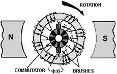
Figure 2-6. - Gramme-ring armature. 2-7
To check the direction of rotation of this armature, you should use the right-hand rule for motors.
Hold your thumb, forefinger, and middle finger at right angles. Point your forefinger in the direction of field
flux; in this case, from left to right. Now turn your wrist so that your middle finger points in the direction
that the current flows in the winding on the outside of the ring. Note that current flows into the page (away from
you) in the left-hand windings and out of the page (toward you) in the right-hand windings. Your thumb now points
in the direction that the winding will move. The Gramme-ring armature is seldom used in modem DC motors.
The windings on the inside of the ring are shielded from magnetic flux, which causes this type of armature to be
inefficient. The Gramme- ring armature is discussed primarily to help you better understand the drum-wound
armature. DRUM-WOUND ARMATURE The drum-wound armature is generally used in AC motors. It is
identical to the drum winding discussed in the chapter on DC generators. If the drum-wound armature were
cut in half, an end view at the cut would resemble the drawing in figure 2-7, (view A), Figure 2-7, (view B) is a
side view of the armature and pole pieces. Notice that the length of each conductor is positioned parallel to the
faces of the pole pieces. Therefore, each conductor of the armature can cut the maximum flux of the motor field.
The inefficiency of the Gramme-ring armature is overcome by this positioning.
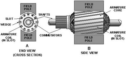
Figure 2-7. - Drum-type armature. The direction of current flow is marked in each conductor in figure 2-7, (view A) as though the armature
were turning in a magnetic field. The dots show that current is flowing toward you on the left side, and the
crosses show that the current is flowing away from you on the right side. Strips of insulation are
inserted in the slots to keep windings in place when the armature spins. These are shown as wedges in figure 2-7,
(view A).
Q10. Why is the Gramme-ring armature not more widely used? Q11. How is the disadvantage of the
Gramme-ring armature overcome in the drum-wound armature? 2-8
DirectION of ROTATION The direction of rotation of a DC motor depends on the direction of the magnetic field and the direction of
current flow in the armature. If either the direction of the field or the direction of current flow through the
armature is reversed, the rotation of the motor will reverse. However, if both of these factors are reversed at
the same time, the motor will continue rotating in the same direction. In actual practice, the field excitation
voltage is reversed in order to reverse motor direction. Ordinarily, a motor is set up to do a particular
job that requires a fixed direction of rotation. However, there are times when it is necessary to change the
direction of rotation, such as a drive motor for a gun turret or missile launcher. Each of these must be able to
move in both directions. Remember, the connections of either the armature or the field must be reversed, but not
both. In such applications, the proper connections are brought out to a reversing switch. Q12. In a DC
motor that must be able to rotate in both directions, how is the direction changed? MOTOR SPEED A motor whose speed can be controlled is called a variable-speed motor; DC motors are variable- speed motors.
The speed of a DC motor is changed by changing the current in the field or by changing the current in the
armature.
When the field current is decreased, the field flux is reduced, and the counter EMF decreases. This permits more
armature current. Therefore, the motor speeds up. When the field current is increased, the field flux is
increased. More counter EMF is developed, which opposes the armature current. The armature current then decreases,
and the motor slows down.
When the voltage applied to the armature is decreased, the armature current is decreased, and the motor again
slows down. When the armature voltage and current are both increased, the motor speeds up. In a shunt
motor, speed is usually controlled by a rheostat connected in series with the field windings, as shown in
figure 2-8. When the resistance of the rheostat is increased, the current through the field winding is decreased.
The decreased flux momentarily decreases the counter EMF. The motor then speeds up, and the increase in counter
EMF keeps the armature current the same. In a similar manner, a decrease in rheostat resistance increases the
current flow through the field windings and causes the motor to slow down.

Figure 2-8. - Controlling motor speed. 2-9
In a series motor, the rheostat speed control may be connected either in parallel or in series with
the armature windings. In either case, moving the rheostat in a direction that lowers the voltage across the
armature lowers the current through the armature and slows the motor. Moving the rheostat in a direction that
increases the voltage and current through the armature increases motor speed. Q13. What is the effect on
motor speed if the field current is increased? ARMATURE REACTION You will remember that the subject of armature reaction was covered in the previous chapter on DC generators.
The reasons for armature reaction and the methods of compensating for its effects are basically the same for DC
motors as for DC generators. Figure 2-9 reiterates for you the distorting effect that the armature field
has on the flux between the pole pieces. Notice, however, that the effect has shifted the neutral plane backward,
against the direction of rotation. This is different from a DC generator, where the neutral plane shifted forward
in the direction of rotation.
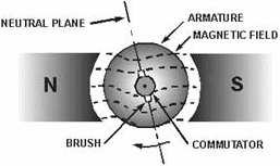
Figure 2-9. - Armature reaction. As before, the brushes must be shifted to the new neutral plane. As shown in figure 2-9, the shift is
counterclockwise. Again, the proper location is reached when there is no sparking from the brushes. Q14.
Armature reaction in a DC motor causes a shift of the neutral plane in which direction? Compensating
windings and interpoles, two more "old" subjects, cancel armature reaction in DC motors. Shifting brushes reduces
sparking, but it also makes the field less effective. Canceling armature reaction eliminates the need to shift
brushes in the first place. Compensating windings and interpoles are as important in motors as they are in
generators. Compensating windings are relatively expensive; therefore, most large DC motors depend on interpoles
to correct armature reaction. Compensating windings are the same in motors as they are in generators. Interpoles,
however, are slightly different. The difference is that in a generator the interpole has the same polarity as the
main pole AHEAD of it in the direction of rotation. In a motor the interpole has the same polarity as the main
pole FOLLowING it.
2-10
| - |
Matter, Energy,
and Direct Current |
| - |
Alternating Current and Transformers |
| - |
Circuit Protection, Control, and Measurement |
| - |
Electrical Conductors, Wiring Techniques,
and Schematic Reading |
| - |
Generators and Motors |
| - |
Electronic Emission, Tubes, and Power Supplies |
| - |
Solid-State Devices and Power Supplies |
| - |
Amplifiers |
| - |
Wave-Generation and Wave-Shaping Circuits |
| - |
Wave Propagation, Transmission Lines, and
Antennas |
| - |
Microwave Principles |
| - |
Modulation Principles |
| - |
Introduction to Number Systems and Logic Circuits |
| - |
- Introduction to Microelectronics |
| - |
Principles of Synchros, Servos, and Gyros |
| - |
Introduction to Test Equipment |
| - |
Radio-Frequency Communications Principles |
| - |
Radar Principles |
| - |
The Technician's Handbook, Master Glossary |
| - |
Test Methods and Practices |
| - |
Introduction to Digital Computers |
| - |
Magnetic Recording |
| - |
Introduction to Fiber Optics |
| Note: Navy Electricity and Electronics Training
Series (NEETS) content is U.S. Navy property in the public domain. |
|


