| - |
Matter, Energy,
and Direct Current |
| - |
Alternating Current and Transformers |
| - |
Circuit Protection, Control, and Measurement |
| - |
Electrical Conductors, Wiring Techniques,
and Schematic Reading |
| - |
Generators and Motors |
| - |
Electronic Emission, Tubes, and Power Supplies |
| - |
Solid-State Devices and Power Supplies |
| - |
Amplifiers |
| - |
Wave-Generation and Wave-Shaping Circuits |
| - |
Wave Propagation, Transmission Lines, and
Antennas |
| - |
Microwave Principles |
| - |
Modulation Principles |
| - |
Introduction to Number Systems and Logic Circuits |
| - |
- Introduction to Microelectronics |
| - |
Principles of Synchros, Servos, and Gyros |
| - |
Introduction to Test Equipment |
| - |
Radio-Frequency Communications Principles |
| - |
Radar Principles |
| - |
The Technician's Handbook, Master Glossary |
| - |
Test Methods and Practices |
| - |
Introduction to Digital Computers |
| - |
Magnetic Recording |
| - |
Introduction to Fiber Optics |
| Note: Navy Electricity and Electronics Training
Series (NEETS) content is U.S. Navy property in the public domain. |
NEETS Module 17 - Radio-Frequency Communications Principles
Pages i,
1-1,
1-11,
2-1,
2-11,
2-21,
2-31,
3-1,
3-11,
3-21,
3-31,
3-41,
4-1- to 4-10,
4-11,
5-1,
5-11, Index
Chapter 2
Introduction to Communications THEORY
Learning Objectives
Upon completion of this chapter you will be able to: 1. Describe the four basic types of
transmitters. 2. Describe the two basic types of single-sideband circuits.
3. Describe the three basic types of teletypewriter circuits. 4. List the four
primary functions of a basic receiver. 5. Describe the four primary functions of a basic
receiver. 6. State the four characteristics of a basic receiver. 7.
Evaluate the four characteristics of a basic receiver. 8. Describe the fundamental
heterodyning process. 9. Describe the basic difference between an AM and an FM receiver.
10. Describe single-sideband suppressed carrier communications. 11. State the
purpose of carrier reinsertion and how it is used in single-sideband communications. 12.
Describe the basic theory and functions of receiver control circuits. 13. Describe the basic
frequency synthesis process. 14. Describe the basic audio reproduction process.
Introduction
In the previous chapter you learned the fundamentals of U.S. naval telecommunications and communications. Now,
let's look at the equipment and systems that are used to communicate in the Navy. The fundamental equipment used
to communicate are the transmitter and receiver. Transmitters and receivers must each perform two basic
functions. The transmitter must generate a radio frequency signal of sufficient power at the desired frequency. It
must have some means of varying (or modulating) the basic frequency so that it can carry an intelligible signal.
The receiver must select the desired frequency you want to receive and reject all unwanted frequencies. In
addition, receivers must be able to amplify the weak incoming signal to overcome the losses the signal suffers in
its journey through space. Representative transmitters and their fundamental features are described for
you in this module.
2-1
Transmitter FUNDAMENTALS Basic communication transmitters include continuous
wave (CW), amplitude modulated (AM), frequency modulated (FM), and single sideband (SSB) types. a basic
description of each of these transmitters is given in this chapter. CONTINUOUS WAVE Transmitter
The continuous wave is used principally for radiotelegraphy; that is, for the transmission of short or long pulses
of RF energy to form the dots and dashes of the Morse code characters. This type of transmission is sometimes
referred to as interrupted continuous wave. CW transmission was the first type of radio communication used, and it
is still used extensively for long-range communications. Two of the advantages of CW transmission are a narrow
bandwidth, which requires less output power, and a degree of intelligibility that is high even under severe noise
conditions. (For example, when the receiver is in the vicinity of rotating machinery or thunderstorms.) A
CW transmitter requires four essential components. These are a generator, amplifier, keyer, and antenna. We have
to generate RF oscillations and have a means of amplifying these oscillations. We also need a method of turning
the RF output on and off (keying) in accordance with the intelligence to be transmitted and an antenna to radiate
the keyed output of the transmitter.
Let's take a look at the block diagram of a CW transmitter and its power supply in figure 2-1. The oscillator
generates the RF carrier at a preset frequency and maintains it within close tolerances. The oscillator may be a
self-excited type, such as an electron-coupled oscillator, or a quartz crystal type, which uses a crystal cut to
vibrate at a certain frequency when electrically excited. In both types, voltage and current delivered by the
oscillator are weak. The oscillator outputs must be amplified many times to be radiated any distance.
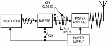
Figure 2-1. - CW transmitter block diagram.
The buffer stage or first intermediate power amplifier stage (referred to as the ipa) is a voltage amplifier
that increases the amplitude of the oscillator signal to a level that drives the power amplifier (pa). You will
find the signal delivered by the buffer varies with the type of transmitter and may be hundreds or thousands of
volts.
The buffer serves two other purposes. One is to isolate the oscillator from the amplifier stages. Without a
buffer, changes in the amplifier caused by keying or variations in source voltage would vary the load of the
oscillator and cause it to change frequency. It may also be used as a frequency multiplier, which is explained
later in this text.
2-2
As you can see in the figure, a key is used to turn the buffer on and off. When the key is closed, the RF
carrier passes through the buffer stage; when the key is open (buffer is turned off), the RF carrier is prevented
from getting through. The final stage of a transmitter is the power amplifier (referred to as the pa). In
chapter 3 of NEETS, Module 1, Introduction to Matter, Energy, and Direct Current, you learned that power is the
product of current and voltage (P = IE). In the power amplifier a large amount of RF current and voltage is made
available for radiation by the antenna. The power amplifier of a high-power transmitter may require far
more driving power than can be supplied by an oscillator and its buffer stage. One or more low-power intermediate
amplifiers are used between the buffer and the final amplifier that feeds the antenna. The main difference between
many low- and high-power transmitters is in the number of intermediate power-amplifier stages used. Figure
2-2 is a block diagram of the input and output powers for each stage of a typical medium- power transmitter. You
should be able to see that the power output of a transmitter can be increased by adding amplifier stages capable
of delivering the power required. In our example, the .5 watt output of the buffer is amplified in the first
intermediate amplifier by a factor of 10, (this is a times 10 [´ 10] amplifier) giving us an input of 5 watts to
the second intermediate amplifier. You can see in this example the second intermediate amplifier multiplies the 5
watt input to it by a factor of 5 (´ 5) and gives us a 25 watt input to our power (final) amplifier. The final
amplifier multiplies its input by a factor of 20 (´ 20) and gives us 500 watts of power out to the antenna.

Figure 2-2. - Intermediate amplifiers increase transmitter power.
Q1. What are the four basic transmitter types? Q2. What is the function of the
oscillator in a CW transmitter? Q3. What is the final stage of a transmitter?
Amplitude MODULATED Transmitter In AM transmitters, the instantaneous amplitude of the RF
output signal is varied in proportion to the modulating signal. The modulating signal may consist of many
frequencies of various amplitudes and phases, such as the signals making up your own speech pattern.
Figure 2-3 gives you an idea of what the block diagram of a simple AM transmitter looks like. The oscillator,
buffer amplifier, and power amplifier serve the same purpose as those in the CW transmitter. The microphone
converts the audio frequency (AF) input (a person's voice) into corresponding electrical energy. The driver
amplifies the audio, and the modulator further amplifies the audio signal to the amplitude necessary to fully
modulate the carrier. The output of the modulator is applied to the power
2-3
amplifier. The pa combines the RF carrier and the modulating signal in the power amplifier to produce
the amplitude-modulated signal output for transmission. In the absence of a modulating signal, a continuous RF
carrier is radiated by the antenna.
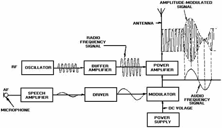
Figure 2-3. - AM radiotelephone transmitter block diagram.
Frequency MODULATED Transmitter In frequency modulation (FM) the modulating signal
combines with the carrier to cause the frequency of the resultant wave to vary with the instantaneous amplitude of
the modulating signal. Figure 2-4 shows you the block diagram of a frequency-modulated transmitter. The
modulating signal applied to a varicap causes the reactance to vary. The varicap is connected across the tank
circuit of the oscillator. With no modulation, the oscillator generates a steady center frequency. With modulation
applied, the varicap causes the frequency of the oscillator to vary around the center frequency in accordance with
the modulating signal. The oscillator output is then fed to a frequency multiplier to increase the frequency and
then to a power amplifier to increase the amplitude to the desired level for transmission.
2-4
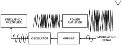
Figure 2-4. - FM transmitter block diagram.
Harmonics True harmonics are always exact multiples of the basic or fundamental
frequency generated by an oscillator and are created in amplifiers and their associated circuits. Even harmonics
are 2, 4, 6, and so on, times the fundamental; odd harmonics are 3, 5, 7, and so on, times the fundamental. If an
oscillator has a fundamental frequency of 2,500 kilohertz, the harmonically related frequencies are 5,000………………second harmonic 7,500………………third harmonic 10,000………………fourth
harmonic 12,500………………fifth harmonic
You should note that the basic frequency and the first harmonic are one and the same. The series
ascends indefinitely until the intensity is too weak to be detected. In general, the energy in frequencies above
the third harmonic is too weak to be significant. In some electronics books, and later in this chapter,
you will find the term SUBHarmonic used. It refers to a sine wave quantity (for example, an oscillator output)
that has a frequency that is a submultiple of the frequency of some other sine wave quantity it helped make. For
example, a wave that is half the fundamental frequency of another wave is called the second subharmonic of that
wave; one with a third of the fundamental frequency is called a third subharmonic; and so forth. Q4.
What purpose does a microphone perform in an AM transmitter? Q5. In an FM transmitter, when
does an oscillator generate only a steady frequency? Q6. What is a harmonic? Q7.
If the fundamental frequency is 200 megahertz, what is the third harmonic?
2-5
Frequency Multiplication Designing and building a stable crystal oscillator is
difficult. As operating frequencies increase, the crystal must be ground so thin that it often cracks while
vibrating. You will find that you can get around this problem by operating the oscillators in most transmitters at
comparatively low frequencies, sometimes as low as 1/100 (.01) of the output frequency. You raise the oscillator
frequency to the required output frequency by passing it through one or more frequency multipliers. Frequency
multipliers are special power amplifiers that multiply the input frequency. Stages that multiply the frequency by
2 are called doublers; those that multiply by 3 are triplers; and those multiplying by 4 are quadruplers.
You will find the main difference between low-frequency and high-frequency transmitters is the number of
frequency-multiplying stages used. Figure 2-5 shows the block diagram of the frequency- multiplying stages of a
typical Navy uhf/vhf transmitter. The oscillator in this transmitter is tunable from 18 megahertz to 32 megahertz.
You have multiplier stages that increase the oscillator frequency by a factor of 12 through successive
multiplications of 2, 2, and 3.

Figure 2-5. - Frequency multiplying stages of a typical vhf/uhf transmitter.
Figure 2-6 is a block diagram of an FM transmitter showing waveforms found at various test points. In
high-power applications you often find one or more intermediate amplifiers added between the second doubler and
the final power amplifier.
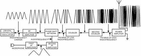
Figure 2-6. - Block diagram of an FM transmitter and waveforms.
2-6
Single-SIDEBand Transmitter You should remember the properties of modulation
envelopes from your study of NEETS, Module 12, Modulation Principles. a carrier that has been modulated by voice
or music is accompanied by two identical sidebands, each carrying the same intelligence. In amplitude-modulated
(AM) transmitters, the carrier and both sidebands are transmitted. In a single-sideband transmitter (SSB), only
one of the sidebands, the upper or the lower, is transmitted while the remaining sideband and the carrier are
suppressed. SUPPRESSION is the elimination of the undesired portions of the signal. Figure 2-7 is the
block diagram of a single-sideband transmitter. You can see the audio amplifier increases the amplitude of the
incoming signal to a level adequate to operate the SSB generator. Usually the audio amplifier is just a voltage
amplifier.
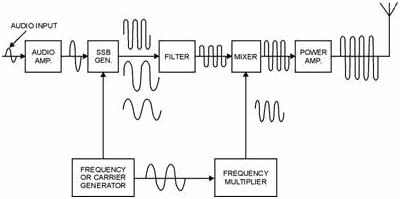
Figure 2-7. - SSB transmitter block diagram.
The SSB generator (modulator) combines its audio input and its carrier input to produce the two sidebands. The
two sidebands are then fed to a filter that selects the desired sideband and suppresses the other one. By
eliminating the carrier and one of the sidebands, intelligence is transmitted at a savings in power and frequency
bandwidth.
In most cases SSB generators operate at very low frequencies when compared with the normally transmitted
frequencies. For that reason, we must convert (or translate) the filter output to the desired frequency. This is
the purpose of the mixer stage. a second output is obtained from the frequency generator and fed to a frequency
multiplier to obtain a higher carrier frequency for the mixer stage. The output from the mixer is fed to a linear
power amplifier to build up the level of the signal for transmission. Suppressed Carrier
In SSB the carrier is suppressed (or eliminated) at the transmitter, and the sideband frequencies produced by
the carrier are reduced to a minimum. You will probably find this reduction (or elimination) is the most difficult
aspect in the understanding of SSB. In a single-sideband suppressed carrier, no carrier is present in the
transmitted signal. It is eliminated after modulation is accomplished and is reinserted at
2-7
the receiver during the demodulation process. All RF energy appearing at the transmitter output is
concentrated in the sideband energy as "talk power." After the carrier is eliminated, the upper and lower
sidebands remain. If one of the two sidebands is filtered out before it reaches the power amplifier stage of the
transmitter, the same intelligence can be transmitted on the remaining sideband. All power is then transmitted in
one sideband, instead of being divided between the carrier and both sidebands, as it is in conventional AM. This
provision gives you an increase in power for the wanted sideband. You should note in figure 2-8 that the bandwidth
required for the SSB suppressed carrier, view B, is approximately half that needed for conventional AM, view A.
This enables us to place more signals in a smaller portion of the frequency spectrum and permits a narrower
receiver bandpass.
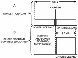
Figure 2-8. - Comparison of bandwidths of conventional AM and SSB voice channels.
Applications Single-sideband transmission is the most common communications mode used
today. Some of the SSB applications used in naval communications are described for you in the following
paragraphs.
SSB VOICE Circuits. - The high command (HICOM) network uses SSB as a means of communications
between fleet commanders; and fleet commanders use it for communications between their subordinates and adjacent
commands.
SSB is generally used whenever special voice communications circuits are necessary between shore activities or
between ships and shore activities because it is less susceptible to atmospheric interference than amplitude
modulation.
SSB TELETYPEWRITER Circuits. - With few exceptions, you will find SSB used on all long- haul (great
distance) teletypewriter circuits, which includes ship-to-shore. Most of these systems are covered circuits; that
is, an electronic cryptographic device on both ends of the circuit automatically encrypts and decrypts message
traffic. These devices are used on point-to-point, ship-to-shore, ship-to- ship, and broadcast circuits.
2-8
Point-to-Point. - Most point-to-point, long-haul circuits between naval communications
stations quickly use up the available frequency spectrum that SSB provides. Independent sideband (IsB)
transmission is normally used to compensate for the deficiency. IsB is used extensively in naval communications to
expand our traffic capabilities. You will find there is a similarity between SSB and IsB. IsB uses outputs from
two sideband generators; it suppresses both carriers and then filters out an upper sideband from one and a lower
sideband from the other. We then combine the two remaining sidebands and transmit an envelope with upper and lower
sidebands that contain different intelligence. IsB can be used with MULTIPLEXING (a method for simultaneous
transmission of two or more signals over a common carrier wave) to transmit a lot of intelligence on one circuit.
Independent sideband and multiplexing will be discussed in more detail in chapter 3. Ship-to-Shore. - Many
ships handle enough message traffic to justify ship-to-shore teletypewriter circuits. Depending on traffic load,
these circuits may contain from one to four (minimum) teletypewriter circuits on one sideband circuit. If the
traffic load warrants more than one teletypewriter circuit, we usually use time division multiplex or frequency
division multiplex (mux) equipment. This equipment is capable of handling many incoming and outgoing circuits. One
circuit normally is used as an ORDERWire Circuit for operator-to-operator service messages and for making
frequency changes when necessary. The remaining circuits are available for handling official message traffic.
Q8. Why are frequency multipliers used?
Q9. What are two advantages of SSB transmission? Q10. What is the purpose of an
order-wire circuit? Ship-to-Ship. - Ship-to-ship SSB teletypewriter circuits are in wide use today. Their main application is with task force or task group networks or with several ships in company. By
using this type of network, ships can send their outgoing messages to another ship that relays traffic ashore. You
can see this procedure saves manpower and circuit time, prevents individual ships from overcrowding ship-to-shore
circuits, and conserves the frequency spectrum. Depending on the number and types of ships in company, the guard
can be shifted to other ships from time to time. a major advantage of these circuits is that electronic
cryptographic devices can be used to send classified messages without need for manual encryption. These circuits
are used for incoming as well as outgoing traffic, and they can use either hf or uhf communications equipment.
RECEIVER FUNDAMENTALS
An AM receiver processes amplitude-modulated signals received by its antenna. It delivers an output that is a
reproduction of the signal that originally modulated the RF carrier at the transmitter. The signal can then be
applied to some reproducing device, such as a loudspeaker, or to a terminal device, such as a teletypewriter.
Actual AM receivers vary widely in complexity. Some are very simple; others contain a large number of complex
circuits.
Functions Whatever its degree of sophistication, a receiver must perform certain basic
functions to be useful. These functions, in order of their performance, are reception, selection, detection, and
reproduction.
2-9
Reception Reception occurs when a transmitted electromagnetic wave passes
through the receiver antenna and induces a voltage in the antenna. Selection
Selection is the ability of the receiver to select a particular frequency of a station from all other station
frequencies appearing at the antenna of the receiver. Detection Detection is the
action of separating the low (audio) frequency intelligence from the high (radio) frequency carrier. a detector
circuit is used to accomplish this action. Reproduction Reproduction is the
action of converting the electrical signals to sound waves, which can then be interpreted by your ear as speech,
music, and the like. An example of this might be the stereo speakers in your car. RECEIVER
Characteristics
Sensitivity, noise, selectivity, and fidelity are important receiver characteristics. These characteristics will
be useful to you when performing receiver tests. They can help you to determine whether a receiver is working or
not or in comparing one receiver to another. Sensitivity The ability of a
receiver to reproduce weak signals is a function of the sensitivity of a receiver. The weaker a signal that can be
applied to a receiver and still produce a certain value of signal output, the better the sensitivity rating.
Sensitivity of a receiver is measured under standardized conditions. It is expressed in terms of the signal
voltage, usually in the microvolts that must be applied to the antenna input terminals to give an established
level of the output. The output may be an ac or dc voltage measured at the detector output or a power measurement
(measured in decibels or watts) at the loudspeaker or headphone terminals. Noise
All receivers generate a certain amount of noise, which you must take into account when measuring sensitivity.
Receiver noise may originate from the atmosphere (lightning) or from internal components (transistors, tubes).
Noise is the limiting factor of sensitivity. You will find sensitivity is the value of input carrier voltage (in
microvolts) that must be applied from the signal generator to the receiver input to develop a specified output
power. Selectivity
Selectivity is the degree of distinction made by the receiver between the desired signal and unwanted signals. You
will find the better the ability of the receiver to reject unwanted signals, the better its selectivity. The
degree of selection is determined by the sharpness of resonance to which the frequency- determining circuits have
been engineered and tuned. You usually measure selectivity by taking a series of sensitivity readings. As you take
the readings, you step the input signal along a band of frequencies above and below the circuit resonance of the
receiver; for example, 100 kilohertz below to 100 kilohertz
2-10
|


