Braided Flexible Coax

Semi-Rigid Coax
Most professional engineers and technicians will never have the need to calculate
the capacitance, inductance, or impedance of a coaxial cable since they are usually
designing systems using well-defined components that are manufactured to exacting
specifications. Students, hobbyists (Ham radio operators), and research types are
probably the ones most likely to actually plug numbers into a calculator. For those
people, I present these equations. Be very careful to realize that at frequencies
far from DC, factors like skin depth and effective inner and outer conductor diameters
may be significantly different than the physical measured values, and that can significantly
affect real world results. Therefore, be sure to consult manufacturers' published
data before making a final decision. I leave it to other sources to provide the
complex equations needed to precisely model coaxial cables.

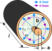
a = outside radius of inner conductor
(inches)
b = inside radius of outer conductor
(inches)
c = speed of light in a vacuum = 299,792 km/s = 186,282 mi/s
ε = dielectric constant = ε0
* εr
ε0 = permittivity of free space = 8.85419
x 10-12 F/m
εr = relative dielectric constant
μ = 4π x 10-7
H/m
μr = relative permeability
These equations are used in
Espresso Engineering Workbook™.


Note:
a and
b
can be in any units of length as long as they are both the same.


Note:
a and
b
can be in any units of length as long as they are both the same. However,
l
must be in the units shown.
Note:
a and
b
can be in any units of length as long as they are both the same.
C
has units of Farads and
L
has units of Henries.
ln =
loge, log = log10


Note:
V has the same length units as
c.


Note:
a and
b
must be in units of length shown.
Note: This is the amount of phase rotation per unit length.


Note:
Γ is unitless.
VSWR
is written as a
VSWR:1 ratio.
Equations for coaxial cable attenuation used to be offered here, but while re-designing
this page and attempting to verify the equations, I discovered (or probably re-discovered)
that theoretical values versus published measured values for real-world cable varied
a lot at every frequency. RG6 coax, for example, can have a loss at 1 GHz ranging
from a little over 5 dB/100 feet to nearly 10 dB/100 feet, depending
on the dielectric type, actual conductor and dielectric diameters, and it seems
very importantly, the construction of the outer shield conductor. A single layer
of loosely woven braid versus a one or more dense layer(s) of braid and one or more
layer(s) of metal foil versus semi-rigid versus hardline coaxial cable makes calculation
using a simple, one-size-fits-all equation impossible.
Therefore, I have removed the equations I used to have and instead recommend
that you visit coaxial
cable manufacturers' websites and consult their published data and decide what
value of attenuation per foot, meter, etc., is most appropriate for your real-world
applications.
Posted August 25, 2021
(updated from original
post on 6/2/2005)
Related Pages on RF Cafe - Coaxial Cable
Specifications - Capacitor Dielectrics & Descriptions
- Dielectric Constant, Strength, &
Loss Tangent - Conductor Bulk Resistivity & Skin
Depths - Coaxial Cable Equations -
Coaxial Cable Specifications -
Coaxial Cable Vendors - Coaxial Resonator -
Coaxial Connector Usage Chart
|


