|
July 1963 Electronics World
 Table of Contents
Wax nostalgic about and learn from the history of early electronics. See articles
from
Electronics World, published May 1959
- December 1971. All copyrights hereby acknowledged.
|
Most RF Cafe visitors are
familiar with the negative resistance region exhibited in tunnel diodes. It is what
makes them usable, among other special applications, as oscillators. Although a
diode is often part of an AC circuit, it is fundamentally thought of as a DC device
since it permits conduction in only one direction (the exception being a Zener diode). An
AC device in general refers to something used in a line supply circuit at 50 Hz,
60 Hz, or even 400 Hz. Such is the case with this article, which
describes negative resistance characteristics of voltage-variable capacitors (varactor)
and ferroresonant devices like saturable coils.
See author's "Negative Resistance: What It Is & How It's Used" article in
the May 1961 Electronics World.
A.C. Negative-Resistance Devices
Description of ferroresonators, nonlinear-type capacitors, semiconductor capacitors,
and other similar components.
By Rufus P. Turner
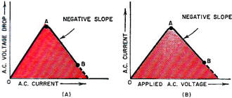
Fig. 1. Basic curves of the a.c. negative-resistance devices
discussed below.
The author's earlier article on negative resistance was devoted to direct-current
devices.1 However, that article stated in conclusion that certain a.c.
devices also exhibit the property of negative resistance, or negative impedance.
This article describes devices of this type.
For simplicity's sake, throughout this article the term "negative resistance"
will be used in a generic sense. But the reader will recognize that the negative
quantity may be impedance or reactance, rather than resistance.
Such a.c. negative-resistance devices are not nearly as numerous as the d.c.
devices, but we may reasonably expect additions to the family as research and development
continue. The external manifestations of a negative characteristic are substantially
the same in a.c. and d.c. devices, that is, the conduction curve has a negative
slope over some part of it. In one instance, current will be the independent variable;
in another, voltage will be. Thus in Fig. 1A, current is the independent variable.
As the a.c. current is continuously increased, the a.c. voltage drop across the
device first increases from 0 to A and then decreases (showing a negative resistance)
from A to B. In Fig. 1B, voltage is the independent variable. As the applied
a.c. voltage is continuously increased, the a.c. current flowing through the device
first increases from 0 to A, and then decreases (showing negative resistance) from
A to B.
The following sections describe the action of devices which exhibit one or the
other of these conduction characteristics.
Ferroresonator
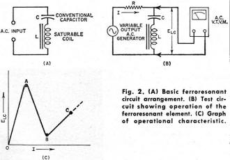
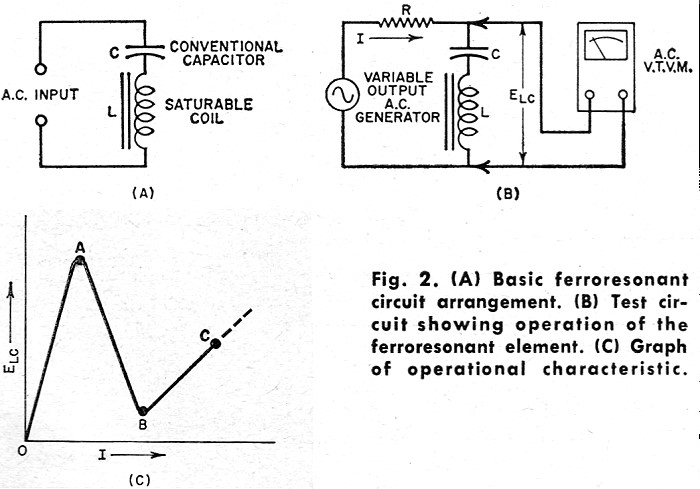
Fig. 2. (A) Basic ferroresonant circuit arrangement. (B)
Test circuit showing operation of the ferroresonant element. (C) Graph of operational
characteristic.
The ferroresonator (also called "ferroresonant circuit," saturable-reactor switch,"
and "ferristor") is a special type of series-resonant LC circuit. It really is quite
simple, consisting only of a coil and capacitor connected in series (see Fig. 2A).
The capacitor is a conventional one but the coil is not. The special feature of
the coil is its core which saturates readily. Because of core saturation, the inductance
and reactance of the coil decreases as the current is increased. An ordinary iron-core
filter choke will exhibit saturation and a resulting decrease in inductance if current
is raised high enough, but this usually requires a rather large current at power-line
frequencies. A ferroresonator coil intended for operation between 100 kc. and several
megacycles, however, is wound on a tiny, thin core of high-permeability metal and
will saturate on only a few milliamperes.
The LC combination resonates at a frequency, fr, determined by the
inductance and capacitance values. (Resonant frequency  . Capacitance C is constant,
but inductance L varies with the current, I, flowing through the circuit, so the
resonant frequency changes with current. (As I increases, L decreases, and fr
increases.) This is the basis of Ferroresonator operation. . Capacitance C is constant,
but inductance L varies with the current, I, flowing through the circuit, so the
resonant frequency changes with current. (As I increases, L decreases, and fr
increases.) This is the basis of Ferroresonator operation.
Fig. 2B shows a typical ferroresonant circuit. Here resistance R is non-inductive.
The generator provides an adjustable a.c. output voltage. By adjusting the voltage,
the operator varies current I flowing through R, L, C in series. The voltage (ELC)
across the LC combination is measured with a high-impedance a.c. vacuum-tube voltmeter.
Fig. 2C shows circuit response. As the current is steadily increased, voltage
ELC rises to a peak (point A), then decreases to a valley (point B),
and finally rises again to C and beyond. Thus, AB is a negative-resistance region
bounded by two positive-resistance regions (0A and BC). This is a typical negative-resistance
curve.
The circuit behavior may be explained in the following manner. (1) The L and
C values are selected to give a resonant frequency somewhat lower than the generator
frequency. Increasing the current decreases inductance L and tunes the circuit up
to the generator frequency and finally to some still higher frequency. (2) As I
is increased from zero, ELC rises and would continue to do so if the
core of the coil did not begin to saturate. Saturation (starting at point A in Fig. 2C)
lowers the inductance and tunes the circuit toward resonance at the generator frequency.
(3) At generator resonance, the net reactance of the LC combination is theoretically
zero, therefore ELC is theoretically zero. As resonance is approached,
ELC accordingly decreases. At resonance (point B), ELC does
not drop fully to zero because resistance losses remain to act in the circuit after
resonant cancellation of the reactance. (4) As I is increased further, core saturation
increases, inductance lowers still more, and the circuit is tuned to a frequency
higher than the resonant frequency. Thus, the voltage once more rises - in this
case from B to C.
Tiny r.f. ferroresonators have been used as active elements in flip-flops, electronic
counters, gates, and other computer-type devices.2,3,4 They also have
been employed as magnetic amplifiers at audio frequencies. In these particular units,
C usually is a fairly small mica capacitor, while L is a coil that has been wound
on a core of Permalloy foil.
Nonlinear Capacitor Element
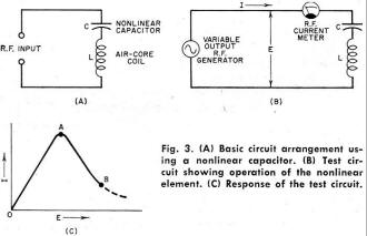
Fig. 3. (A) Basic circuit arrangement using a nonlinear capacitor. (B) Test
circuit showing operation of the nonlinear element. (C) Response of the test circuit.
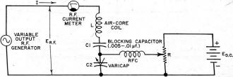
Fig. 4. Alternative circuit with a semiconductor capacitor.
Fig. 3A shows a series-resonant negative-resistance circuit which resembles
the ferroresonant circuit described in the preceding section but behaves somewhat
differently. This arrangement uses a conventional air-core coil and a nonlinear
(voltage-variable) capacitor. Suitable capacitors of this type contain a high-K
ceramic dielectric, such as specially processed single-crystal barium titanate.
As the voltage applied to the capacitor is increased, the capacitance decreases.
As in the standard ferroresonant circuit, the L and C values in Fig. 3B
are selected so that the zero-voltage resonant frequency of the circuit is lower
than the generator frequency. As the voltage is increased, the current rises from
zero to a peak point (A in Fig. 3C). As the voltage is increased further, the
current decreases. Thus, the current-voltage curve has a negative slope from A to
B.
Behavior of the circuit may be explained in this manner. (1) The increasing voltage
lowers the capacitance and tunes the LC circuit up toward the resonant frequency
(generator). The current increases because increasing capacitive reactance causes
the net reactance of the circuit to decrease. (2) At resonance with the generator,
the net reactance is theoretically zero, and maximum current flows. This corresponds
to point A in Fig. 3C. (3) As the voltage is increased beyond this point, the
circuit is tuned to frequencies higher than resonance. The capacitance continues
to fall but the net reactance of the circuit increases, so the current decreases.
This is represented by the negative slope, AB.
Semiconductor Capacitor Circuit
A ceramic nonlinear capacitor, such as C in Fig. 3, usually requires relatively
high-voltage operation for appreciable capacitance change. Furthermore, such capacitors
are quite temperature-sensitive because of the Curie point of the dielectric material.
To obtain low-voltage operation (from a few tenths of a volt to 1 to 6 volts r.m.s.)
and at the same time to secure comparative freedom from temperature effects, semiconductor
voltage-variable capacitors may be substituted in the circuit, as shown in Fig. 4.
Response is the same as that shown in Fig. 3C.
In Fig. 4, the semiconductor voltage-variable capacitor (also known as Varicap,
varactor, Semicap, etc.) is d.c.-biased in a reverse direction to set its initial
capacitance to a desired value and to prevent positive peaks of the maximum r.f.
voltage from driving the semiconductor junction into the low-resistance forward
direction. C1 is a blocking capacitor to keep d.c. out of the current meter and
generator. As in the preceding example, values of L and C2 are chosen for zerosignal
resonance below the generator frequency. Because the capacitance of C1 is very high
with respect to that of C2, it has negligible effect on circuit tuning.
Nonlinear Parallel-Resonant Circuit
Fig. 5. Parallel resonance with a nonlinear circuit element.
It is well known that the current in the line supplying a parallel-resonant circuit
dips to a low value when the circuit is tuned to resonance at the generator frequency.
If a voltage-tuned element is included in the parallel-resonant circuit, the circuit
will then resonate at only one value of input voltage. The line current will then
decrease at this voltage level, showing a negative slope.
Fig. 5A shows a circuit for displaying this negative-resistance effect.
The parallel-resonant circuit is composed of air-core coil (L) and a 56 pf. (μμf.)
Varicap semiconductor voltage-variable capacitor (C2). C1 is a blocking capacitor
(0.005 to 0.01 μf.) whose capacitance is so high with respect to C2 that only
the latter determines the circuit tuning. The values of L and C2 are chosen such
that the zero-signal-voltage resonant frequency of the circuit is somewhat lower
than the generator frequency. As the generator voltage (ER.F.) is increased,
the current (IR.F.) increases from zero to point A in Fig. 5B. The
increasing voltage reduces the capacitance of C2. At the particular level of signal
voltage, the corresponding C2 value tunes the circuit to resonance at the generator
frequency, and the line current dips to point B. As the voltage is increased further,
the capacitance decreases still more, tuning the circuit above resonance, and the
current again rises to point C and beyond. Along the negative slope, AB, the current
is decreasing as voltage is increasing.
For best results, the generator frequency should not be lower than 20 mc. The
higher the frequency, the more pronounced is the negative-resistance effect.
Diodes at Higher Frequencies
At high radio frequencies, the combined action of nonlinear capacitance and a.c.
rectification provided by the semiconductor voltage-variable capacitor gives rise
to an a.c. negative-resistance effect (as well as to hysteresis, in some cases).
Heizman has described a microwave setup in which the capacitor diode is operated
in a tunable waveguide.5 The negative resistance and hysteresis obtained
with this arrangement have been utilized for switching at microwave frequencies.
The response curve is similar to those of Figs. 1B and 3C.
The conventional point-contact germanium diode has been known to exhibit negative
resistance at very high frequencies.
North observed that individually welded whisker diodes showed this effect when
used as v.h.f. superhet converters.6
Such a.c. negative resistance has been observed in some conventional diode tubes
operated at u.h.f.7,8 This is a secondary effect resulting from electron
transit time in the tubes. The mechanism involves the dynamic plate resistance of
the diode, which decreases at ultra-high frequencies. When the transit time equals
the period (1/f) of the applied voltage, Rp = 0. At higher values
of transit time, Rp is first above then below zero, its oscillating curve
showing a negative slope in some portions.
Feedback Amplifiers
An amplifier provided with the proper amount of positive feedback may present
negative resistance to circuitry connected to its input terminals. This applies
to amplifiers of all types, such as vacuum-tube, transistor, magnetic, dielectric,
and varactor. It is this very property that is utilized so widely in oscillating
and regenerative circuits; the negative resistance provided by the feedback amplifier
cancels the losses of the tank circuit into which it operates. A familiar example,
in which loss cancellation results in a large increase in figure of merit, is the
"Q"-multiplier.
The grounded-grid amplifier operates very effectively as an a.c. negative-resistance
device and has been exploited in telephony as a two-way repeater.
A general limitation of all a.c. negative-resistance devices is their requirement
of an a.c. supply, which is sometimes inconvenient and which always limits the maximum
speed at which the device operates. When a.c. supply and circuitry are already provided,
however, or the application is of an a.c. nature to start with, and the supply frequency
is high enough to permit maximum desired operating speed, a.c. negative-resistance
devices offer distinct advantages.
References
1. Turner, Rufus P.: "Negative Resistance: What It Is & How It's Used,"
Electronics World, May 1961.
2. Isborn, Carl: "Ferroresonant Flip-Flops" Electronics, April 1952
3. Rutishauser, R. W.: "Ferroresonant Flip-Flop Design," Electronics, May 1954.
4. Triest, W. E.: U.S. Patent No. 2,709,757 (May 31, 1955).
5. Heizman, C. L.: "Microwave Bistable Circuits Using Varactor Diodes," Proceedings
of the IRE, April, 1961.
6. Torrey. H. C. & Whitmer, C. A.: "Crystal Rectifiers," McGraw-Hill Book
Co., New York, 1948, pgs. 362, 391.
7. Llewellyn, F. B. & Bowen, A. E.: "The Production of Ultra-high-frequency
Oscillations by Means of Diodes," Bell System Technical Journal, April 1939.
8. McPetrie, J. S.: "A Diode for Ultra-H-F Oscillations," Experimental Wireless
and Wireless Engineer, March 1934.
Posted February 7, 2017
|