|
April 1969 Electronics World
 Table of Contents
Wax nostalgic about and learn from the history of early electronics. See articles
from
Electronics World, published May 1959
- December 1971. All copyrights hereby acknowledged.
|
The introduction of low cost,
small-footprint ceramic filters were unquestionably a boon to efforts at reduction
in end-product package size and manufacturing cost. Very good Q and selectivity,
no tuning required, and good temperature stability made them perfect for use as
IF filters in broadcast radio receivers, at 10.7 MHz (FM) and 455 kHz
(AM). They became available for commercial use around 1960. This publically available
paper published in 2000 from the IEEE provides some historical perspective to ceramic
filters:
The History of Ceramic Filters, by Satoru Fujishima.
The Clevite Corporation, for which this Electronics World author, Reg
Zimmerman worked, is mentioned in the IEEE paper, as is Murata, for being
pioneers in the ceramic filter field.
Ceramic Filters

The author joined Clevite in 1958 as Sales Engineer for the Piezoelectric
Division, subsequently moving to the Brush Instruments Division of the form. He
rejoined the Piezo-electric Div. in 1965. He received his BEE from the University
of Detroit. During World War II he served as Communications and Navigation Officer
with the Navy in the Pacific.
By Reg Zimmerman / Clevite Corp.
Filters like these are a "must" for high-density packaging. An extremely high
performance level and rugged construction boosts equipment efficiency.
The trend in military and commercial communications equipment for minimized components
using IC integration has created a demand for extremely small filters that are rugged,
reliable, and have relatively high sensitivity.
Filters made of ceramic, the newest material for the fabrication of bandpass
filters, have these characteristics. For example, a filter with seventeen high-"Q"
tuned circuits for bandwidth ratios of 1.1 to 1 from 70 dB to 6 dB attenuation can
be packed in a 0.312-inch diameter tube less than 1.6 inches long.
The uniqueness of the ceramic filter results from the properties of the lead
zirconate-lead titanate resonators. These resonators have a mechanical "Q" of 450
or 1600, depending on the particular composition. In addition, ceramic resonators
are piezoelectric - by bending, squeezing, and twisting, the material directly converts
mechanical movement to electrical energy. By reversing the process, it converts
electrical energy into mechanical movement. The high electro-mechanical coupling
provides wide-band filters with low insertion loss.
Typically, ceramic disks which measure about 0.2 inch in diameter by 0.010 to
0.040 inch thick resonate at 455 kHz.
How Do They Compare?
Ceramic Filters: Ceramic filters have been developed to operate
at frequencies from 40 Hz to 10.7 MHz. As was mentioned earlier, ceramic resonators
have "Q's" of 450 and 1600. The higher "Q" materials make narrower bandwidth filters
feasible. Higher "Q" materials also reduce insertion loss.
The stability of ceramic is 0.2% of the center frequency from -40°C to +85°C.
This is equivalent to the best grade of LC filters, but not as good as mechanical
or quartz filters. This can be offset by two design techniques. First, due to the
steep sides of ceramic filters, the 6-dB bandwidth can be widened to allow for temperature
change. Second, since the frequency change with temperature is a percentage of the
center frequency, lowering the center frequency will reduce frequency shift. Thus,
a 500-kHz ceramic filter has the same stability as a 15-MHz quartz filter.
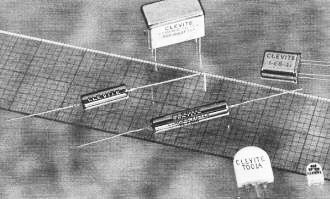
Fig. 1 - These ceramic filters operate from 9 to 50 kHz
and from 300 to 770 kHz. They are ideal for high-density packaging.

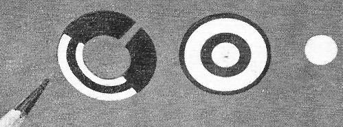
Fig. 2 - A group of resonators. (Left) resonates at 9 kHz,
(center) at 167 kHz, and small one on the right at 455 kHz.
LC Filters: LC filters can be used over a wide frequency range,
but their limiting factors are temperature stability (dependent on core material)
and "Q". In general, "Q" (c.f.) / 3 dB (bandwidth) is less than 100 for LC filters.
Powdered iron cores have good stability but low permeability, lowering the "Q" of
the inductor. Ferrite cores, on the other hand, offer higher permeability but at
the expense of temperature stability. Also, low-frequency filters require large
cores, thus increasing weight and size. One more point, the low "Q" in LC filters
produces a filter with a higher insertion loss when sections are cascaded to steepen
the sides of the passband.
Mechanical Filters: Mechanical filters have a "Q" of 7000 and
excellent temperature stability. These properties favor narrow-band filters (less
than 1%) such as single-sideband filters. However, the mechanical filter requires
a transducer to convert electrical energy to mechanical energy and another transducer
to reconvert the mechanical energy to electrical energy. This, in turn, increases
insertion loss.
Quartz Filters: Quartz filters have "Q's" ranging from 50,000
to 100,000. Their temperature stability is excellent, but they are generally more
expensive than LC or ceramic filters. Bandwidths are usually limited to less than
1% of center frequency unless broadbanding inductors are used. However, competitively
priced products are available at 10.7 MHz.
Three Designs
Currently, three resonator designs are used in manufacturing the filters shown
in Fig. 1. The split ring shown in Fig. 2 resonates at 9 kHz but it can
be tuned to 50 kHz by widening the slot. This thin disk, which has an inductance
value equivalent to about 50 henrys, vibrates at its resonant frequency by the expansion
and contraction of the slot.
The center thin disk vibrates radially at its overtone frequency, popularly 455
kHz. If operated in its fundamental mode, it would vibrate at 167 kHz. Differences
in the electrode area on a given disk result in an impedance transformation so that
the filters of this type can replace the common i.f. transformer, yielding higher
"Q", smaller size, greater temperature stability, and greater selectivity.
The small-sized disk (at right) is the basic resonator used for oscillator control
and for ladder filters. It utilizes the radial mode of vibration, i.e., it expands
and contracts radially. Its resonant frequency is determined by its diameter.
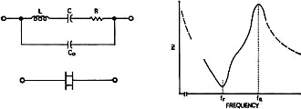
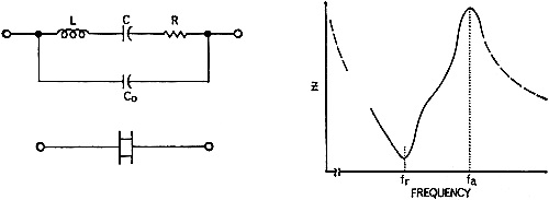
Fig. 3 - Circuit and performance curve of ceramic resonator.
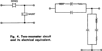
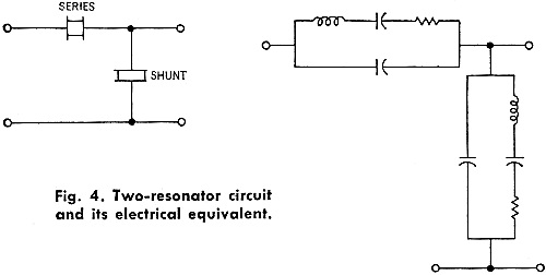
Fig. 4 - Two-resonator circuit arid its electrical equivalent.
A fully electroded disk has an overtone at 2.3 times its fundamental frequency
which can be suppressed or enhanced by varying the area the electrode covers. The
center of the disk is a vibrational node point. Electrical connections are made
by pressure contacts at the center of the disk. The equivalent circuit and the curve
of impedance versus frequency are shown in Fig. 3.
In single-resonator circuits, the equation for the 3-dB bandwidth point is B
= fo / QL, where fo is the center
frequency and QL is the loaded "Q".
Single resonators can be used to control oscillator frequencies or to replace
emitter-bypass capacitors and sharpen the frequency response of transistor radio
receivers.
Generally, two or more resonators are required to develop the desired bandpass
characteristics. The basic two-resonator circuit and its electrical equivalent circuit
are shown in Fig. 4.
The two-resonator section is referred to as an L-section. Assuming 455-kHz is
the desired fo, by tuning the 10K-impedance point (fr)
of the series resonator and the high impedance (fa) of the shunt
resonator to fo, the minimum signal attenuation will be at
fo. Likewise, the points of maximum signal attenuation will
be at fa of the series resonator and fr
of the shunt resonator. If resonators with the same Δf are used,
the attenuation curve illustrated in Fig. 5 will result.
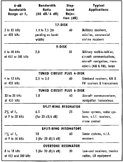
Table 1. Specifications and applications of resonators.
The Co of the individual resonator is determined by the electroded
area, the dielectric constant, and the disk thickness. At frequencies above and
below the high attenuation poles, both resonators act like a capacitance divider.
The larger the ratio Cshunt / Cseries, the larger the attenuation
in the stopband. Since the resonator "Q", fr, Δf,
and Co are all variable in the manufacturing process, center frequency,
the passband width, and the attenuation pole locations can be varied simply and
inexpensively.
The nine-disk and seventeen-disk ladder filters are electrically connected L-sections
with an extra series resonator at the end to make the input and output impedances
equal. Since ceramic filters have their maximum attenuation just above and below
the passband, they offer maximum rejection to adjacent signals. Most LC and quartz
filters have their maximum attenuation points at frequencies of zero and infinity.
Therefore, ceramic filters in the second i.f. of double-conversion receivers complement
the attenuation pattern of the r.f. stage and the first i.f. and greatly improve
the receiver's characteristics. Ceramic ladder filters have stop-band attenuations
from 50 dB to 90 d B, depending on the model. The stop bands are free of spurious
responses from d.c. to 2.3 times the passband frequency.
Ladder filters are simple to use. They are especially designed to match resistive
loads of 1000 to 2500 ohms, depending on the model; and are suitable for use with
transistorized circuitry (see Fig. 6).
Specifying Parameters
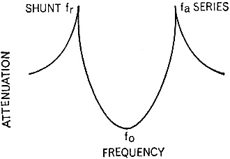
Fig. 5 - Response curve of the two-resonator circuit shown
in Fig. 4.
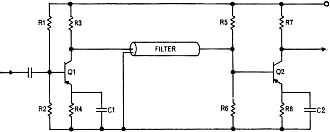
Fig. 6 - Ladder filters are designed to match the resistive
loads of 1000 to 2500 ohms found in transistorized circuits.
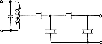
Fig. 7 - 60-dB stopband in a narrow-band filter can be achieved
when a tuned LC circuit is combined with four resonators.
When calling out ceramic filter parameters, the design engineer should specify
minimum stopband attenuation, maximum insertion loss, and maximum passband ripple
as with other filters types. He should, however, also call out the minimum 6-dB
and the maximum 60-dB bandwidths.
Generally, filter impedance level is set by the manufacturer and is a function
of center frequency and bandwidth and hence cannot be specified by the designer.
The designer should be aware that the filter's center frequency and bandwidth
changes over the operating temperature range. For instance, center frequency of
a 500-kHz filter will change a maximum of 1 kHz (0.2%) over the temperature range
-40° C and +85° C. The 6-dB bandwidth is usually designed so that over this
temperature range it stays larger than the minimum specification. In the frequency
range 300 kHz to 700 kHz, the 6-dB bandwidth achievable with ceramic filters range
from approximately 0.5% of center frequency to 20% of center frequency.
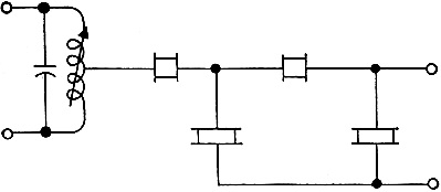
One of the lowest-cost filters designed by Clevite combines a tuned LC circuit
with resonators having the maximum capacitance divider ratio. Thus, four resonators
in a narrow-band filter design achieve 60-dB stopband attenuation; six resonators
are required for wideband filters. The schematic of this low-cost unit is shown
in Fig. 7 and Table 1 lists its specifications and applications as well as
those of some other typical units.
Because ceramic filters are small in size, very rugged, fixed tuned, and extremely
reliable, their future is bright.
Ceramic filters are competitively priced and are rapidly making inroads in low-cost
entertainment equipment. They are especially attractive since they do not require
the installation alignment of conventional tuned circuits.
Ceramic filters have already replaced larger, more expensive LC and mechanical
filters in many mobile, portable, and Citizens Band receivers. They have also repeatedly
proven themselves in military equipment as the most selective and rugged filters
for their size and weight.
Posted December 20, 2017
|