|
April 1969 Electronics World
 Table of Contents
Wax nostalgic about and learn from the history of early electronics. See articles
from
Electronics World, published May 1959
- December 1971. All copyrights hereby acknowledged.
|
By the time you get into the realm
of microwaves, wavelengths are so short that using discrete components for reactive elements
is impractical or impossible. That is where the "magic" of electromagnetic fields kicks
in. Prior to the advent of computer simulators, the design, construction, and adjustment
of distributed element printed circuit boards and waveguide were not for the feint of
heart. Whereas "seat-of-the-pants" tactics often resulted in a successful circuit, guesswork
was (and still is) too expensive in terms of time and materials to be employed in the
spectrum at and above microwaves (approximately 2 GHz). This article from a 1969 issue
of Electronics World magazine is one of ten in a special section on electrical
filters.
Filters for Microwaves
By Robert Felsenheld, Jr./ Engineering Manager, Microlab/FXR

The author joined Microlab/FXR in 1959 and in his present position
is responsible for the coordination of all filter and custom product design and development
contracts. Prior to joining the company, he was associated with ITT Federal Laboratories
where he was involved in the development of communications and radio navigation equipment.
He received his BSEE from Lafayette College in 1958 and an MSEE from Newark College of
Engineering in 1962. He is a member of the IEEE and the IEEE Professional Groups on Microwave
Theory and Techniques and Circuit Theory. He is also a member of Tau Beta Pi and Eta
Kappa Nu honorary groups.
No new breakthroughs; just better made parts. Here's what the system engineer should
consider when choosing a new microwave filter design.
Microwave filters are unique. The frequency spectrum they cover is quite large, overlapping
into the area of lumped-constant filters at the low end and into the "millimeter wave"
region at the upper end. There is some confusion because most engineers and scientists
cannot agree where the microwave frequency spectrum really begins or ends. For traditional
reasons, however, and probably for reasons developed by the industry itself, the practical
microwave region starts at 100 MHz and runs up to frequencies in excess of 18 GHz.
Types of Microwave Filters
Microwave filter types include high-pass, low-pass, and bandpass units whose bandwidths
range from a fraction of a percent to an octave or even more; narrow- and wideband band-reject
types; elliptic function filters with extremely steep rates of rejection; complementary
filter pairs; continuous channel diplexers; combination networks to act as channel separating
and multiplexing devices; lossy wall and mode suppressing filters; directional filters
which have the properties of directional couplers but exhibit bandpass and band-reject
characteristics depending on which ports are chosen as input and output; and filters
used for phase correction networks and delay lines. Types and applications are a never
ending list.
What Makes a Microwave Filter?
Anyone who has worked in the lower frequency regions or with an FM or TV tuner knows
the problems that can be encountered due to stray capacitances or excessive component
lead lengths. Microwave filters overcome these difficulties somewhat by the use of distributed
rather than lumped elements. Thus, the microwave filter engineer uses transmission line
lengths and characteristic impedances rather than commercial capacitors and coils as
the elements of design. In the v.h.f. and u.h.f. regions, there is overlapping and some
combining of the lumped-element and distributed-element design. These filters are classed
as "hybrids." At higher frequencies almost all filters are constructed of parts made
on lathes and milling machines.
In the past ten years, microwave filters have undergone a vast change. The major stimulus
to this change has been the tremendous activity generated toward what is called "modern
network theory" as opposed to the older and more pragmatic "image parameter" method of
design. Modern network theory has not only made possible practical bandpass, low-pass,
high-pass, and band-reject filters to more optimum specifications, but also has led to
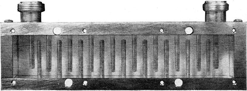
a variety of new types and configurations. Two examples of distributed-element bandpass
structures are shown in Figs. 1 and 2. Fig. 1 is a 19-resonator interdigital filter constructed
of alternately shorted round-rod quarter-wavelength resonators in a metal housing. Fig.
2 is a five-resonator comb-line device constructed of parallel-coupled, capacitive-shortened
rectangular resonators in a metal housing. In both cases, the filters could have been
constructed from round rod, rectangular rod, or strip-line. For the interdigital filter,
each rod or resonator is the microwave equivalent of a low-frequency "tank circuit."
For the combline filter, the same is true, except the input and output bars act as transformer
sections, not resonators. These are only two examples of devices which are popular in
microwave systems.
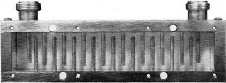
Fig. 1 - A 19-resonator interdigital filter made of alternately shorted
quarter-wavelength rod resonators in metal housing.
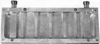
Fig. 2 - Five-resonator comb-line filter using capacitance tuning.
Other technologies, the call for miniaturization, and economic pressures have all
influenced microwave filter technology. Some filters can be fabricated using printed-circuit
strip-line techniques. A strip-line filter is, in itself, not a type of filter but a
type of construction. Many types of microwave filters can be constructed in printed strip-line,
but most strip-line filters are of the moderate and wideband bandpass type. Printed strip-line
filters are designed utilizing distributed elements, as were the comb-line and interdigital
previously discussed. But printed strip-line elements more often take the form of open
or short-circuit quarter-, half-, or three-quarter wavelength stubs of varying widths.
Typically these stubs are interconnected by quarter-wavelength coupling lines to yield
the desired design characteristic. Recently, printed strip-line filters have replaced
their fabricated, thick-strip predecessors in some system applications, but printed-circuit
filter components probably account for less than five percent of all microwave filter
component applications. Strip-line filters are more often used with other printed-circuit
devices such as directional couplers, mixers, hybrids, etc., where all the components
may be integrated and reproduced on one circuit board. Two major drawbacks to printed-circuit
filters (and possibly the reasons why they are not used as much as one might think) are
bandpass insertion loss and temperature instability. These factors are dependent on the
nature of the filter, and upon the resistive losses and thermal characteristics of the
dielectrics of the copper-clad materials which are presently available in the industry.
Helical-line filters have become quite popular below 1000 MHz because the slow-wave
property of the helix (it takes r.f. energy longer to travel circularly along a helix
than along an equivalent length of coaxial transmission line) permits length and volume
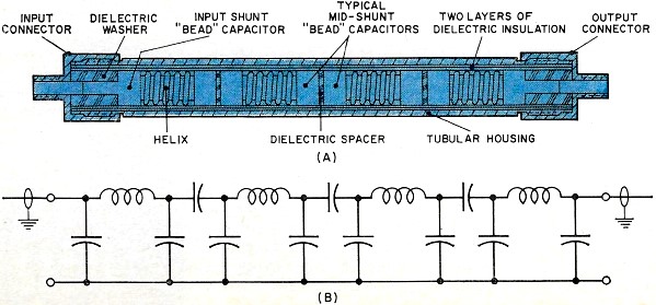
savings on the order of three times or more. Fig. 3A shows a typical four-resonator helical
tubular bandpass filter. The design is "hybrid" in nature. The "coils" are actually distributed
elements which have been precisely calculated as lengths of helical transmission line.
Each helix is soldered to two adjacent shunt bead capacitors which have predetermined
values and are calculated as dielectrically loaded concentric coaxial cylinders. These
two capacitors and one helix form one resonator. The resonators are coupled to one another
through dielectric spacers which are located between the faces of adjacent beads. The
input and output capacitors are shunt elements. The lumped-element equivalent circuit
diagram is shown in Fig. 3B. Because of this configuration, helical tubular bandpass
filters have a steep (slope) rate of rejection at the upper frequency cut-off point and
a reduced rate on the lower frequency rejection slope. A filter such as the one illustrated
is typically about four inches long and one-half inch in diameter at 400 MHz.
YIG filters are a newer type of filter which finds application in some systems. Yttrium
iron garnets are used to construct miniature cavities (YIG filters) which can be electrically
tuned over octave bandwidths.
Some Microwave Filter Characteristics
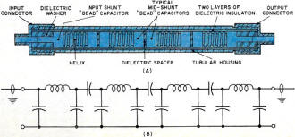
Fig. 3 - This hybrid filter (A) and its equivalent circuit (B) is
typical of helical tubular band-pass types.
Microwave filters have some special characteristics and exhibit some phenomena not
normally associated with filters at other frequencies. This is true despite the fact
that the design theory is exactly the same as that used at all other frequencies. Most
coaxial systems are 50-ohm systems, therefore most coaxial filters quite naturally are
specified with 50-ohm input and output impedances. Some v.h.f. systems are 72 ohms or
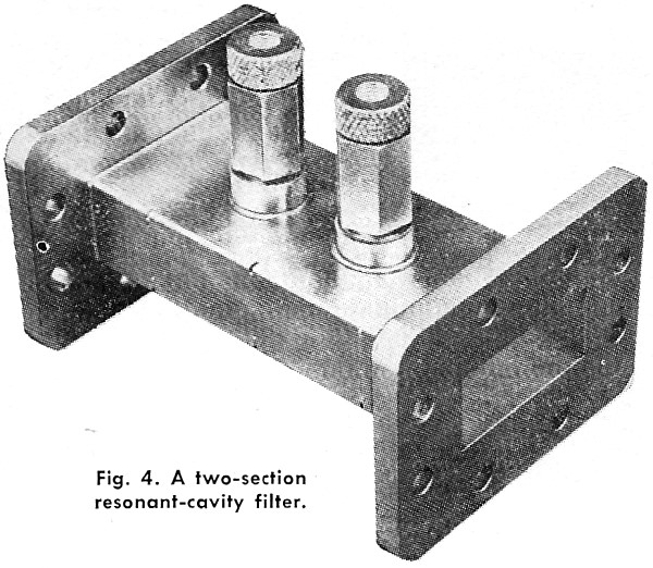
93 ohms. On the other hand, waveguide filters are not normally specified by impedance,
but rather by waveguide size. Thus the typical two-section cavity shown in Fig. 4 would
be specified to work over a frequency range in WR-137. This is because the true impedance
of the waveguide is not constant but varies with frequency and therefore is not a practical
parameter.
"Q", or unloaded "Q" is not usually a problem in microwave filters. The geometries,
configurations, and boundaries required by microwave structures usually assure a reasonable
"Q" is available. In the worst cases, insufficient "Q" will be translated into an undesired
passband insertion loss. In multi-resonator filters, "predistortion loss" associated
with finite "Q" and predictable as a function of phase slope or group time delay will
cause additional transmission losses at passband edges.
Temperature drift can be a problem with microwave filters, particularly with narrow-band
cavity devices. These filters are typically used as preselectors in microwave receivers.
Cavities are normally temperature-compensated in the mechanical design or constructed
of relatively temperature stable materials such as invar, a nickel-steel alloy. Moderate
or wideband devices do not demonstrate as much deterioration of performance or frequency
drift in severe temperature environs except possibly in systems which require a high
degree of absolute and relative phase and group time delay stability.
As was previously stated, microwave filters are designed from the same basic theory
as all other resonant devices, and therefore tabulated information about rejection curves,
shape factors, passband ripples, "Q", phase, insertion loss, etc. is also applicable
to all microwave filters.
How to Select & Specify a Microwave Filter
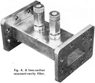
Fig. 4 - A two-section resonant-cavity filter.
It is important for an individual who selects and specifies a microwave filter to
recognize the special properties of certain filter types. For example, low-pass microwave
filters mayor may not be required to pass signal from d.c. to some cut-off frequency,
fc, but the stopband must have some finite upper limit, i.e., six to ten times
fc. The upper limit of the reject band will, therefore, not extend to infinite
frequency.
Microwave high-pass filters have rather special properties. In fact, there is no such
thing as a true microwave high-pass filter! This is due to the distributed nature of
the elements. A microwave high-pass filter is actually a wideband bandpass filter or
pseudo-high-pass filter. Thus, although the band may reject d.c. to some desired frequency,
the actual passband will extend from some cut-off frequency, fc, to some other
finite frequency, fh, but does not continue indefinitely to some higher operating
frequency.
Waveguide filters can cause problems because each standard waveguide range covers
only a relatively small portion of the frequency spectrum, or a useful frequency range
of roughly thirty percent. On the low side, the waveguide itself cuts off and behaves
like a high-pass filter. Above the useful range, energy propagates in modes other than
the fundamental TE10 mode, and thus structures which are designed to work
within a given waveguide range are only useful in or below that range. A waveguide band-reject
filter will not pass frequencies below the waveguide's cut-off point even though it may
yield the desired "notch" and close-in passband performance.
Microwave filter users should be aware of the limitations of typical coaxial and strip-line
structures. Filters such as those shown in Figs. 1 and 2 are designed using distributed
techniques and, in general, these structures become periodic with frequency. Typically,
microwave bandpass filters constructed with quarter-wavelength resonators exhibit additional
passbands at odd harmonics of their center frequencies. Bandpass filters constructed
of half-wave resonators exhibit additional passbands at all harmonics. Low-pass filters
or elements are often used in conjunction with bandpass structures to eliminate harmonic
problems. Coaxial and strip devices can also exhibit mode problems (i.e., spurious responses
in their reject bands) when the dimensions of their structures become significant compared
to a wavelength at some higher frequency. A good filter designer will consider these
problems, based on the specification given.
Fortunately, all microwave filters irrespective of their type-low-pass, bandpass,
band-reject, etc. - are defined essentially by the same parameters. Thus, the nomenclature
or the specification of parameters becomes relatively simple. The characteristics relating
to the theoretical design or method of synthesis is something for the microwave engineer
to know, understand, and use, but are not necessary knowledge for the systems engineer
(except in sophisticated or very special applications). Thus, the non-filter designer
need not be fretful if such terms as Chebyshev, Butterworth, Butterworth-Thompson, Cauer,
elliptical, or Gaussian-type responses seem foreign to him. Essentially, the microwave
filter user must know "what frequencies are to be passed and what frequencies are to
be stopped, how much loss is allowable in the passband and how much rejection is required
in the stopband." More specifically, the applicable electrical parameters can be set
forth by the following:
1. Passband frequency range
2. Passband insertion loss
3. Passband v.s.w.r. and/or amplitude ripple
4. Average power
5. Peak power
6. Impedance
7. Stopband frequency range
8. Stopband rejection.
9. Phase
10. Group time delay
The last two characteristics were placed at the end purposely because they are only
significant in certain short, fast-rise-time pulse and narrow-band FM systems. The list
neglects two significant parameters not controlled by the filter designer - the source
and load impedances. Uncontrolled source and load impedances can degrade filter performance
and cause voltage breakdowns in a perfectly designed filter. A v.s.w.r. of 1.3:1 for
components or networks adjacent to the filter should give good results.
Make or Buy Your Filter?
Much pressure is being put on systems engineers to design their own filters. At first
glance, there seems to be some valid reasons for this. Miniaturization requirements and
the advent of integrated circuits for the computer and aerospace industries have caused
all technologies to be looked at in other than traditional ways. Strip-line circuitry
has shown the obvious possibility of eliminating connectors between networks or components.
System sophistication has increased the communications and interface difficulties between
contractors and vendors. And, tons of handbook material have been published about microwave
filters in the past several years.
But, a filter should be made in-house only when the proper engineering ability is
available, and then only if there are complementary pragmatic skills available to take
over where the handbooks and theorists leave off. On the other hand, buying a microwave
filter is relatively easy. There are many companies which specialize in microwave filters
and have the facilities to provide certain types of filters as catalogue or near-catalogue
items. At the very least, they can advise on feasibility based on specifications. Thus,
the answer is obvious. It's usually easier and cheaper to buy filters.
The prices of microwave filters depend on the type, the complexity, and the environmental
conditions under which the filter must operate. Typically, tubular filters require less
machine and fabrication time and therefore are normally less expensive than other filters.
Tubular low-pass filters of transmission-line or helical construction sell for just under
$50 to $300. Tubular high-pass and bandpass filters cost between $100 and $400. Basic
waveguide cavity filters may be priced from $250 to $500, but higher-order-mode waveguide
devices can cost $3000. The comb-line and interdigital filters fall in the $250 to $500
category. Tunable coaxial preselectors may cost as much as $750. Printed strip-line filters
may cost between $50 and $200, in quantity, after the initial photography and artwork
costs have been amortized. Incidentally, this pricing information is given as a guide
and the reader should realize actual costs are based on a particular specification.
Future Developments
It is doubtful that revolutionary microwave filter breakthroughs will be made in the
next year. The trend will continue toward miniaturization compatible with 3-mm connectors
through the use of smaller or printed structures. The development of low-loss, high-dielectric
materials should also continue, and there should be increased use of helices and other
slow-wave structures. The big breakthrough will come when microwave transistors become
readily and economically available and can be utilized as a reliable basic building block
in new hybrid or integrated-circuit active microwave filters. Until that time, microwave
filters will probably remain essentially as we know them
Posted December 18, 2017
|