|
April 1967 Electronics World
 Table
of Contents
Table
of Contents
Wax nostalgic about and learn from the history of early electronics. See articles
from
Electronics World, published May 1959
- December 1971. All copyrights hereby acknowledged.
|
The April 1967 edition of
Electronics World magazine had a series of articles about designing systems
with electromechanical relays. Even in today's world of solid state relays, there
are still lots of applications for electromechnical relays. Only a handful of American
companies still make them. The application tutorials provided herein are as
valuable to today's engineers and technicians as they were 55 years ago. This
particular piece covers operate and release times of relays. Other articles in
this issue include
Time-Delay
Relays,
Finding Relay Operate and Release Times, and
Arc, Surge, and Noise Suppression.
Operate and Release Times of Relays

Since graduating from the engineering school at the University
of Kentucky in 1937, the author has held supervisory positions in just about every
production and engineering department at Guardian Electric. From 1960 to 1963 he
served as Chief Design Engineer and has been Assistant Chief Engineer since 1963.
He is a Registered Professional Engineer and holds many patents on relay, switch,
and stepper designs. All too often relays are placed in control and logic circuitry
without enough consideration being given as to whether or not the relay operational
time characteristics will assure proper functioning of the circuit under various
operating conditions. A working knowledge of which factors affect relay operating
time can give the circuit engineer or technician confidence in his design.
By Warren Wright / Asst. Chief Engineer, Guardian Electric Mfg. Co.
Definitions of these important characteristics and methods that are used
to modify these parameters.
In general, relays are electromechanically operated switches, thus there are two
items which must be evaluated when considering the time elements of relay function.
These are the electrical characteristics and the mechanical characteristics.
But first, let's define the terms and then consider their relationship to total
relay function.
Definition of Terms
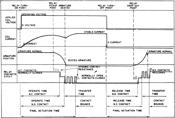
The operate time of a relay is the time interval from the instant of coil-power
application until completion of the last contact function.
The release time is the time interval from the instant of coil-power cut-off
until the completion of the last contact function. (See Fig 1.) Note that the operate
and release times do not include contact-bounce times.
When coil power is applied, coil energizing current increases until the magnetic
flux is sufficient to move the relay armature and its contact-actuating members.
Upon removal of the coil power, magnetic flux does not collapse instantly, but decreases
for some period of time - depending on the circuit, the coil, and the magnetic structure.
When the magnetic flux drops below the "hold-in" value for the particular relay,
the armature and its contact-actuating members return to the normal or de-energized
position.
With these fundamental characteristics in mind, we can now consider the various
relay designs and the effect of circuit characteristics on operate and release times.
D.C. Relays
For d.c. relays, the operate time of a specific relay design may be reduced by
three methods. First, we can overdrive the relay. This is done by increasing the
control voltage, decreasing the coil resistance, increasing the control voltage
and adding a series resistance, discharging a capacitor at an over-voltage charge
into the coil, pre-energizing at some value below pickup voltage (the lowest voltage
at which the relay always operates), using dual-wound coils - one coil for overdrive,
the other to hold the armature in the operated position, using a series resistor
shunted by a capacitor, using a positive temperature coefficient resistor in series
with the coil, and using a series resistor shunted by an N.C. switch - the switch
being operated by the relay being controlled.
Second, we can reduce the pickup voltage of the relay by mechanical means, such
as by reducing return spring pressure, reducing the armature gap, or reducing contact
pressures and gaps.
Third, we can decrease the mechanical inertia by reducing the mass of the moving
elements such as contacts, armature, and contact actuators.
For d.c. relays, the inherent release time of a specific design may be increased
by using a parallel capacitor and series resistor, a parallel shunt resistor or
switch, parallel diode, or by reducing the residual magnetic air gap.
Relay manufacturers produce many varieties of relays with operate and release
times ranging from minimal values of less than one millisecond to some of the more
exotic solid-state relays with maximum times of 30 minutes or more.
Fig. 1 - Typical d.c. operation of a relay with a resistive
d.c. load.
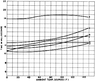
Fig. 2 - Variations in operate or attract times at various
ambient temperatures for six general-purpose d.c. relays.
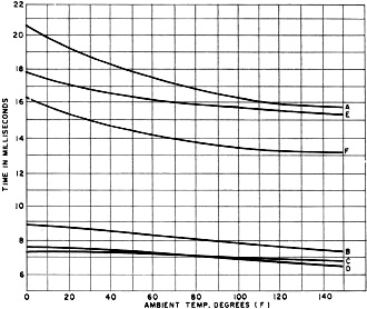
Fig. 3 - Variations in the release times at various ambient
temperatures for the same six general-purpose d.c. relays.
When specific time characteristics are needed, the relay manufacturer can usually
provide relays to match the circuit requirements either from "standard" relays or
as "specials" designed for a specific function.
The National Association of Relay Manufacturers (NARM) has not set standards
with respect to fast or slow response. In general, relays which have operate and
release times under 3 milliseconds are considered fast-operate and/or fast-release.
Relays with function times of 50 milliseconds or more are usually considered slow-operate
or slow-release. Relays with function times between 3 and 50 milliseconds are medium-operate
and release and this is the range into which most general-purpose relays fall. Relays
which are purposely designed for slow function time are classified as time-delay
relays. These are covered in another article in this special section.
Relay manufacturers produce a bewildering range of relays for use in over a hundred
"usage" classifications, with thousands of varieties and modifications in each classification.
It is obviously impractical to analyze all of these types, therefore we will only
cover some of the most popular general-purpose relays.
The graphs of Figs. 2 and 3 show the effects of ambient temperature changes on
the attract and release times of some typical general-purpose, d.c.-powered relays.
From this we can see that the attract or operate time increases with temperature
and the release time decreases with temperature rise (although circuit components
may modify this).
When we consider that relays heat up either under extended energization or repeated
cycling, we can expect a relative shift in operating time characteristics, depending
upon the frequency of operation.
Relays from different manufacturers, but of the same type, generally have similar
operating-time characteristics. It will be noted that some relay types change more
with temperature than others - this is inherent in the design of the relay but.
in general, the time change is within ±10% over an ambient temperature range of
0°F to 160°F.
Other factors affect timing, such as changes in operating voltage or current.
in which the attract time varies inversely with coil power and the release time
varies directly with coil power. Where operation time is critical, the relay should
be evaluated in the circuit under the most adverse combination of variables.
Power-supply inductance will increase the operate time of d.c, relays depending
upon the L/C ratio of the circuit. Resistance in the power-supply line will tend
to decrease the operate time. Relays which are wired in parallel would aggravate
these effects. Arc suppressors or coil shunts will increase the release time of
relays.
Basically, d.c. relays are reasonably consistent in their timing characteristics
under the same operating conditions, but this is not the case with a.c. relays.
A.C. Relays
Other variations in both attract and release times are due to the added factor
of the instantaneous (turn-on or turn-off) voltage change. The source voltage varies
from zero to peak 120 times per second, thus any voltage from zero to peak may be
applied across the coil at the instant of either "turn-on" or "turn-off".
Examination of a typical 60-Hz sine wave will show that most of the time the
instantaneous voltage at "turn-on" or "turn-off" will be higher than the pickup
voltage of the relay, so that the time characteristics are usually within a reasonable
range. Frequently, however, the probability of turning on or off at lesser voltages
catches up with us and the operating time suddenly changes. This voltage variation
is further complicated by the magnetic flux distribution between two or more functional
pole faces. Remember that a.c. relays generally have one core face shaded by a copper
ring to cause a phase displacement in the magnetic flux. This phase shift is necessary
to provide relay hold-in during current reversal. Thus, we have an operational time
range rather than a specific operation time. The manufacturer generally specifies
the average function time for a.c. relays.
Modification of operational time for a.c. relays may be accomplished in a manner
similar to that for d.c. relays, but the actual time of operation will vary because
of the sine-wave voltage applied. We must conclude, therefore, that straight a.c.
relays should not be used in circuits where precise repeatable narrow-range operational
times are required.
The mechanical characteristics which affect operational time apply to both d.c.
and a.c. relays and what affects one type will usually affect the other type in
the same manner.
Increases in mass, whether it be in contact actuators, the contacts, or armature
will slow the operational time. Release time will be increased by minor contact
welding or sticking, mechanical wear, and residual magnetism.
We have not attempted to give charts showing precise operating characteristics
of relays because the timing is subject to so many variables from relay to relay
type, depending upon adjustment, type and number of contacts, voltage variation,
source impedance, line resistance, wear factors, etc. Information on timing characteristics
is available from the manufacturer and should be used whenever operate and release
timing is critical.
Posted March 15, 2022
(updated from original post on 7/3/2012)
|