|
April 1967 Electronics World
 Table
of Contents
Table
of Contents
Wax nostalgic about and learn from the history of early electronics. See articles
from
Electronics World, published May 1959
- December 1971. All copyrights hereby acknowledged.
|
Relays are another topic that never goes out of date. Even with
the advent of fully solid state relays that use semiconductors
in the conduction path, there are still many applications that
only mechanical contacts can satisfy. Very high power, whether
it be high voltage, high current, or both, cannot yet be handled
by semiconductors - at least not economically. Yes, there are
switching diode arrays that can handle very high powers, but
they are typically very expensive. This article is one of a
group of articles about relays in the April 1967 Electronics
World. All will eventually be re-posted here on RF Cafe.
Here are links to the other relay articles:
Operate and Release Times of Relays,
Reed Relays,
Time-Delay Relays,
Finding Relay Operate and Release Times,
Arc, Surge, and Noise Suppression
Time-Delay Relays
By Jerry E. Elpers
Solid-State Products, Potter & Brumfield (Div. American
Machine & Foundry)
The author is presently employed as Solid State Products
Sales Manager. Prior to this, he did circuit design in the Solid
Stale Switching Group. He holds a BSEE from Evansville College,
Evansville, Ind. and has done graduate work at Purdue. He is
a member of IEEE and Sigma Pi Sigma.

Factors to consider in selecting a relay that produces a
predetermined delay. Included is data on thermal, motor-driven,
pneumatic, RC, slugged, hydraulic, escapement, and solid-state
types.
The fantastic growth of the field of automatic industrial
control has increased the demand for new and more versatile
devices to perform the basic electrical switching functions
required. The use of time-delay relays has grown rapidly to
keep pace with the demand for the basic function which they
can perform: that of obtaining a predetermined delay from one
switch operation to another.
Time-delay relays perform in a manner quite similar to a
standard relay in that they have contacts that open and close
when power is applied and removed from the input terminals.
The basic difference is that a delay is incorporated into the
contact opening or dosing. Time-delay relays are used in a wide
range of applications: from determining how full your coffee
cup will be when you put a dime in a vending machine, to shutting
off the cutting oil on a milling machine.
The most popular time-delay relay is the delay on operate,
or de-energization, in which the normally open load switching
contacts transfer at a predetermined time after power is applied
to the input. The contacts drop out immediately upon removal
of the input power (Fig. 1A).
Often a time delay on release, or de-energization, is required.
In this case the normally open load switching contacts operate
immediately when the input power is applied and remain in this
position as long as the input power remains "on". Upon removal
of this power the timing begins, and after a predetermined delay,
the contacts drop out (Fig. 1B).
Several variations on these two basic timing modes are used,
such as interval "on", automatic recycle, combined "on" and
"off" timers, and sequence timers. Many of these can be made
by simple connections of the two basic types.
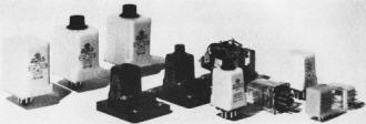
A selection of typical solid-state time-delay
relays, many of which provide an adjustment for the amount of
delay provided.
Factors to Consider
There are many types of time-delay relays available which
will provide the timing action desired, including thermal. motor-driven,
pneumatic, RC circuit, solid-state, slugged, hydraulic, and
escapement.
There are many factors which must be considered when choosing
one of these time-delay relay types. Consideration should be
given to how each fulfills the following criteria: accuracy,
reset time, repeatability, load-switching capabilities, price,
life, mounting configurations, size, length of delay, temperature
effects, and adjustable or fixed time delay.
Also, various time-delay relays have certain peculiarities
in their operation which should be determined in order to select
the type that will do the job reliably and economically, Some
of these peculiarities are covered below.
Thermal Time Delays
The basic operation of this timer takes advantage of the
difference in the thermal expansion of two metals. A bi-metallic
element is placed in close proximity to a heating element, and
when power is applied the bi-metal deforms and closes or opens
a contact. The time required for the contact to operate is generally
determined by the physical characteristics of the bi-metallic
strip and the amount of power applied to the heating element.
Thermal time-delay relays are usually used where a time delay
on energization is required and the accuracy of the time-delay
period is not critical. One manufacturer states an over-all
accuracy of ± 30% for a miniature or octal plug-in timer, with
delays available from 2 to 180 seconds. Another manufacturer
gives accuracies of ± 20% from 0.75 to 1 second, ± 15% from
1 to 4 seconds, and ± 10% for delays up to 360 seconds. This
is also an octal plug-in type time-delay relay.
Contact forms are usually limited to s.p.s.t., N.0. or N.C.
with ratings that normally do not exceed 5 amperes, 115 volts
a.c, resistive (100,000 operations). Since the thermal time
delay uses the I2R heating effect, the device is
somewhat sensitive to input voltage variations. Voltage variations
of ± 10% will change the delay period approximately ± 5%.
The biggest drawback to the thermal time-delay relays is
their long reset time (the time required for the contacts to
open and to achieve an appreciable percentage of the nominal
delay time on the succeeding cycle of operation). This reset
can be as long as 50 to 200 percent of the operate delay in
order to achieve 80% of the nominal delay period on the next
cycle.
One thermal-delay relay manufacturer recommends the use of
an auxiliary relay to overcome this reset time problem. This
unit uses two sets of contacts, one that closes at the end of
the heating interval which pulls in the auxiliary relay and
interrupts the input power. The cooling interval then begins,
after which the second set of contacts drop out completing the
load-switching circuit. Using this method, approximately 85%
of the nominal operate time is achieved on the succeeding cycle.
Most of the better known thermal time-delay relays are of
the plug-in type and range in price from $2 to $20.
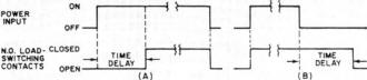
Fig. 1. (A) Delay on energization. (B) Delay
on de-energization.
Pneumatic or Air-Operated
The term "pneumatic" (meaning air-operated) immediately indicates
the basic principle of operation of this type of time delay.
A mechanism is used in which a controlled amount of air under
pressure is displaced from one place to another. (This can be
a unit isolated from the surrounding air, in which the air is
displaced from one chamber to another, or where the air is drawn
from or dispelled into the atmosphere.) A typical unit uses
a diaphragm, a coil, a plunger, and an orifice. When power is
applied to the coil. the plunger (which is mechanically tied
to the diaphragm) is drawn into the coil. The rate of plunger
movement is controlled by the rate of air escape from the diaphragm,
which is controlled by the orifice adjustment. When a predetermined
position is reached, a set of contacts operate as a result of
the plunger movement.
The pneumatic time-delay relay has been in use for 25 years
and has a well-established reputation in heavy industrial applications.
Several manufacturers have units available which lend themselves
to these types of application. They are available for control-panel
mounting, have screw terminals, and are designed for use in
severe industrial environments. This type of time delay is available
as an adjustable unit: some with time-calibrated dials and some
with screwdriver-slot adjustments. The repeat accuracy is usually
± 10% and the reset time is approximately 25 milliseconds (this
reset also applies in case of power interruption).
Units are available in both time delay on energization,
delay on de-energization, and also with both of these functions
packaged in the same enclosure. Some can be converted in the
field from delay on energization to de-energization by a simple
mechanical change. Contact ratings are available up to 20 amperes,
120 V a.c., 60 Hz, resistive (100,000 operations life).
Time-delay periods are available from 0.2 second up to 30
minutes from one manufacturer and 0.050 second to 3 minutes
from another. The temperature range of operation is in the area
from -50° C to +65° C. Supply voltages of 6 V a.c. to 550 V
a.c., 60 Hz and 6 V d.c. to 250 V d.c. are available. Input
power requirements range from 5 to 8 watts. Prices range from
$18 to $100.
Many of the pneumatic units are fairly
large due to the space required for the mechanical mechanism,
although some smaller versions are also available with lower
contact ratings (10 amperes) and shorter delays (180 seconds)
at a higher cost. Pneumatic delays can cause a problem in application
where a dirty atmosphere exists. Any clogging of the orifice
will cause changes in the delay period.
Motor Driven
A synchronous motor is normally used in motor-driven
timers to drive a gear train which controls the load-switching
contacts. When power is applied, the movement functions until
a predetermined time has elapsed, at which time the output contacts
are switched. This timing method depends upon the input line
frequency for its basic accuracy, in a manner similar to a standard
12-hour, 120-V a.c., 60-Hz clock. The majority of these timers
use a magnetic clutch in conjunction with the clock movement
which serves the function of engaging the movement when power
is applied, and allowing it to reset when the power is removed.
The unit is reset by a return spring when the clutch is released.
The time-delay period is set on these units by a pointer
on the front or top of the relay (this may be continuously adjustable
or in increments). A second pointer is usually used to indicate
the elapsed time. The setting accuracy of the continuously adjustable
timers is generally ± 0.5% of full-scale, and the repeat accuracy
is ± 1% of full-scale, or better. The reset time is proportional
to the time required to reset the spring-loaded mechanism and
will be less than 500 milliseconds, depending on time setting
relative to full-scale.
Motor-driven time-delay relays
are available in both delay on energization and delay on de-energization.
The load contacts of the delay on de-energization operate immediately
when power is applied to the clutch and removal of clutch power
starts the timing interval. When this interval is completed,
the contacts drop out. The delay on de-energization will reset
when a momentary power loss occurs.
Delay lengths of
5 seconds to 60 hours are available from one manufacturer and
5 minutes to 5 hours from another. Life ratings of these timers
range from 500,000 operations for one manufacturer to a contact
life rating of 5 million operations for another. Life is usually
limited by clutch failure rather than contact life. Input power
ranges from 5 to 15 VA, including clutch coil and motor. Contact
switching ratings up to 15 amperes continuous are available.
Most of the units available are for 120/240-V a.c., 60-Hz operation.
D.c. units are not generally available. The temperature range
of operation is -20°C to +50°C. Prices range from $5 to $50.
The majority of the motor-drive time-delay relays have
some kind of adjustment feature, some of which are for front-panel
mounting, with a knob to set the time-delay period and are intended
for industrial control-panel use. Others are available with
pointers that can be set to adjust the timing in increments
and are not intended for applications requiring front-panel
mounting.
Delay Slug Relays
A time delay
can be produced on a telephone-type d.c. relay by placing one
or more shorted turns around the magnetic circuit (usually the
core) so as to produce a counter-m.m.f. which retards the build-up
of the operating flux, and upon de-energization provides an
m.m.f. to retard the collapse of the flux. This shorted turn.
or turns. is called a slug. Usually it consists of a copper
collar on the core of the relay. In some designs, a copper sleeve
is used over the full length of the core, and the coil is wound
on the sleeve.
The principle of operation of the slug
is as follows: When the relay coil is energized, the flux build-up
passes through the slug and by self-inductance produces an m.m.f
that opposes the coil m.m.f. This opposing m.m.f. delays the
build-up of the magnetic field in the air gap to a strength
that will cause the armature to close. The time delay on drop-out
occurs in the opposite manner. When the relay coil is de-energized,
the field starts to collapse, thus inducing a current in the
slug that provides an m.m.f. oriented so as to sustain the magnetic
field and thus delay the drop-out.
Pickup delays up
to 120 milliseconds and drop-out delays up to 500 milliseconds
can be achieved by the use of slugs. The delay time will vary
due to mechanical wear over life and ambient temperature and
this type is not intended for high-accuracy applications. Slugged
relays are not generally an off-the-shelf item and are available
only on a special-order basis from most manufacturers of telephone-type
relays.
RC Circuit
Various methods have been
used to devise time delays using combinations of resistors,
capacitors, and relays. All of these circuits use the basic
principle of charge and discharge of a capacitor and one of
the simplest circuits using this principle is shown in Fig.
2A.
When the switch is closed, the capacitor charges
toward the applied voltage and, after a period of time determined
by the resistance and capacitance (assuming the relay coil resistance
to be very large compared to the resistor), the relay pulls
in. When the power is interrupted the capacitor discharges through
the relay at a rate controlled by the size of the capacitor,
the inductance, and the resistance of the relay coil. This circuit
does not produce an accurate time delay since the time is dependent
upon many factors. Variations in the resistance, the capacitance,
the input voltage, and relay pull-in voltage will cause changes
in tile time-delay period. Delay-period accuracies of ± 30%
are to be expected. The reset time is also long, due to the
high-resistance, capacitor-discharge path. In practice these
timers can be purchased with delays up to 30 seconds and in
both a.c. and d.c. versions.
Variations of this basic
circuit are available which use additional components to increase
the accuracy and speed up the reset time. One popular circuit
uses a neon bulb to sense the voltage level on the capacitor
and a photo-resistive cell to drive the relay. The photocell
offers a low impedance in series with the relay when the neon
bulb fires and causes the relay to pull in (Fig. 2B).
This circuit has several advantages over the previous circuit
in that the neon bulb senses an accurate voltage level and does
not rely on the relay pull-in voltage for the accuracy of the
delay. Also, the relay drops out immediately when the power
is removed, and the timing can be reset with another set of
contacts across the capacitor if desired.
This circuit
is used in several commercially available time-delay relays.
The units are generally adjustable (a potentiometer is used
in series with the resistor) , and the enclosure is all octal
plug-in type. The accuracy of this unit is usually stated as
± 10% over a limited temperature range. Relay outputs on these
timers are usually d.p.d.t., 5-ampere, 120-V a.c, resistive.
Solid-State
The latest entries into the
time-delay relay field are the solid-state types. There are
presently two basic types available using entirely different
principles of operation. One manufacturer is marketing a relay
that uses an accurate oscillator and a counter to perform the
timing function. An output from this oscillator is initiated
when power is applied and is fed into an amplifier circuit.
This amplifier shapes the pulses and reeds them to a magnetic-core
counter. When a predetermined count is reached. the output load
switching contacts are operated through a logic circuit. The
time delay period is determined by the logic and by how many
counters are used after the oscillator.
This time-delay
relay is intended for applications where a high degree of accuracy
is required (± 2 %) . The standard operating voltage is from
18 to 82 V d.c, It has either a relay or a solid-state output
and requires 0.4 sec to reset the delay to the stated accuracy.
Enclosures are available with the popular plug-in feature or
with hook solder terminals and a side mounting bracket. This
unit is expensive as time-delay relays go and sells for $100
or more.
The most popular circuit used in solid-state
time-delay relays employs the RC charge principle, mentioned
previously. The reason for the popularity of this method stems
from the use of the unijunction transistor.
The unijunction
transistor has the inherent ability to offer a high input impedance
to the capacitor voltage until a predetermined voltage is reached.
At this point the device fires and discharges the timing capacitor.
The circuit of Fig. 2C can be used to illustrate this
operation. When the switch is closed, the capacitor charges
at a rate controlled by the RC product. At a voltage level controlled
by the unijunction transistor, the capacitor discharges through
the relay coil and causes the relay to operate. This pulse is
only momentary and a set of relay contacts serves to latch in
the relay.
The unijunction circuit has several advantages over the neon-bulb
circuit in that the firing level is proportional to the input
voltage. Therefore, any input voltage variations are compensated
for by a proportionate change in firing voltage. Other devices
call be added to this circuit to overcome some of the deficiencies
of the previous circuits. Zener diodes are added for better
compensation of time changes due to input voltage variations.
An SCR can be added to give the relay more pull-in and hold-in
power.
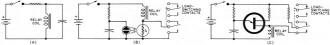
Fig. 2. (A) RC circuit may be used to provide
time delay. (B) Neon bulb and photocell or (C) unijunction transistor
may be used.
The circuit shown in Fig. 2C also has the drawback that the
capacitor will discharge through the relay coil immediately
if the power is interrupted and this causes the relay to pull-in
momentarily. The addition of an SCR eliminates this problem.
Line Transients
One problem peculiar to the solid-state
time delays has been that of line transients, particularly on
time-delay relays used on 120-V a.c. line voltage. These transients,
or momentary overvoltage conditions. are common on a 120-V a.c.
line. They can be produced from a wide variety of conditions
including lightning striking the line, switching of inductive
loads on the line, or making and breaking of the transformer
input supplying the time-delay relay. These transients are usually
not a severe problem because they do not contain much energy.
Solid-state time-delay relays used on a 120-V a.c. line
normally employ a silicon rectifier at the input in order to
produce the required d.c, voltage for time-delay operation.
This rectifier is susceptible to the energy contained in these
transients if the voltage is allowed to exceed its reverse rating.
Two methods are commonly used in better solid-state units to
suppress these transients. One method is the use of a controlled-avalanche
rectifier for this input rectifier. When the reverse input voltage
exceeds the rectifier reverse voltage, the device avalanches
and dissipates the transient energy. Special selenium breakdown
devices are also used which can withstand even more energy.
Transient problems are better understood now than in the past
and adequate protection can be provided.
Since solid-state
time delay relays use transistors in the timing portion, and
transistors have long life, a very reliable timer can be built
using these devices. :Many of the units available have an integral
relay for load switching; typically, d.p.d.t., 10-ampere, 120-V
a.c. resistive. In this case the life is limited to the life
of the relay, usually10 million mechanical operations.
Several manufacturers market an all-solid-state timing module
to drive an external load-switching relay. In this case, the
timer life is nearly infinite and is very useful for applications
where high cycle rates are experienced.
Types Available
Solid-state units are available in fixed delays,
internal potentiometer adjustable delays, and external resistor
adjustable delays. The external resistor can be a potentiometer
mounted remotely and wires run to the delay unit.
A wide range of mounting configurations is available, including
screw-terminal dust covers, plug-in types, hermetically sealed
military types, and panel-mounted types. Units are available
in d.c. voltages from 12 to 100 V d.c. and 24 to 240 V a.c.,
60 Hz and require approximately 3 watts of power. The timing
range is usually limited to delays from 0.10 second to 5 minutes
on commercially available units. Delay accuracy varies from
one manufacturer to another and can be as good as ± 5 % over
the temperature range from -40°C to +55°C, and a voltage range
of ±10%.
Several manufacturers are marketing knob-adjustable
solid-state time-delay relays with time-calibrated dials. The
reset time varies, but is usually fast-from 40 milliseconds
to 100 milliseconds - depending upon the circuit configuration.
Time-delay relays are available in both delay on energization
and on de-energization. (The delay on de-energization requires
an auxiliary source of power during the delay period to hold
in the load switching relay and cannot be used for a momentary
power failure delay.)
The solid-state time-delay relays
are available in small enclosures and range in price from about
$10 to $60.
STEPPING RELAYS
There are two types
of driving mechanisms used in stepping relays (often called
stepping switches): the indirect and the direct.
When
the armature-pawl combination acts directly on the ratchet under
the power of the electromagnet, the device is said to be directly
driven, as shown in Fig. A. When the pawl acts on the ratchet
wheel from force stored in a drive spring, the mechanism is
said to be indirectly driven. An example of this method is shown
in Fig. B. The indirectly driven system is the most commonly
used. The spring-driven system is more consistent in performance,
more efficient, and capable of faster stepping than the directly
driven type, besides having a longer operational life.
In an indirectly driven unit, when the proper voltage and
power is applied to the motor magnet coil, the armature is attracted
and holds the drive spring in the "cocked" position. When the
coil is de-energized, the energy stored in the drive spring
pushes the pawl against a ratchet wheel tooth, causing the wiper
assembly to take a step. Repetitive pulses will cause the switch
to take as many steps as the number of discrete pulses received.
The length of time the circuit is closed (and opened) in a series
of fast pulses is critical.
Self-interrupted operation,
such as shown in Fig. B, is used to step the switch rapidly
from one point to another without the use of discrete pulses
from outside sources. In this method, a circuit is closed to
the coil through a set of interrupter contact springs that are
opened by an arm of the armature before it is fully seated.
Breaking the coil circuit causes the armature to fall away,
driving the wiper assembly one step and simultaneously reclosing
the interrupter contacts. The armature is again attracted, re-cocking
the switch and thus causing a re-opening of the interrupter
contacts. The switch runs self-interruptedly until the circuit
is again opened.
Posted 9/9/2011


