|
April 1969 Electronics World
 Table of Contents
Wax nostalgic about and learn from the history of early electronics. See articles
from
Electronics World, published May 1959
- December 1971. All copyrights hereby acknowledged.
|
The April 1969 issue of Electronics
World magazine featured a collection of ten articles dealing with filter design
and application, authored by experts in the field. This one discusses which filter types
- lumped element (inductors and capacitors), distributed element (stripline, microstrip,
etc.), waveguide, cavity - are best fitted for use based on the intended application.
Power handling, rejection requirements, inband insertion loss, physical size, cost, stability
over time, temperature, vibration, and moisture as common considerations. Sometimes the
decision comes down to designer preference, manufacturing complexity, desire to build
in-house vs. buying a manufactured unit, ability to make minor tweaks during testing
and/or field maintenance.
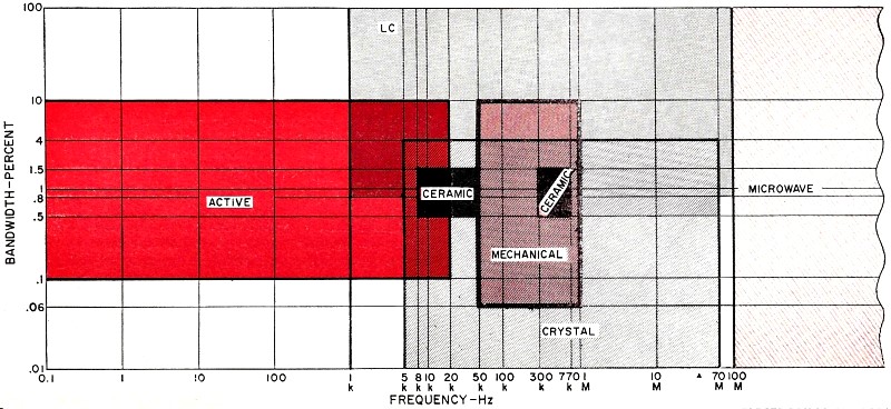
Practical Operating Limits for Filters
 The frequency and percent bandwidth limits for
the different filters shown in the diagram are representative over-all figures. For example,
it should not be inferred that for a crystal filter operating at a center frequency of
10 MHz, all percent bandwidth values listed are realizable. Design trade-offs must be
made to obtain physically realizable and economical units. Because the r.f. interference
filter is an example of an application rather than a type, it is not included in the
frequency diagram. The frequency and percent bandwidth limits for
the different filters shown in the diagram are representative over-all figures. For example,
it should not be inferred that for a crystal filter operating at a center frequency of
10 MHz, all percent bandwidth values listed are realizable. Design trade-offs must be
made to obtain physically realizable and economical units. Because the r.f. interference
filter is an example of an application rather than a type, it is not included in the
frequency diagram.
From 1 kHz to 100 MHz the LC filter covers the largest area of frequency spectrum
and percent bandwidth. At very low (less than 1 kHz) and at very high (greater than 100
MHz) frequencies it is nearly impossible to fabricate LC filters with either useful electrical
characteristics or small physical dimensions. At frequencies less than 1 kHz, inductance
values and physical dimensions become excessive. The active filter, using reasonable
values of RC elements and an operational amplifier, can provide filtering at frequencies
less than a hertz.
For frequencies greater than 100 MHz, discrete LC structures fail as filters because
of parasitic capacitance and inductance. Microwave filters composed of distributed elements
such as transmission lines, waveguides, and comb structures are used at the higher frequencies.
From the frequency diagram, it is evident that the active filter overlaps into the
frequency range from 1 to 20 kHz. Here a choice can be made among a number of different
filter types. Various factors, including percent bandwidth, temperature, shape factor,
and cost, influence the selection of a particular filter type. For percent bandwidths
greater than 10, an LC filter is required. If signal power gain is needed, this can be
obtained only from an active filter. A crystal filter may be the best choice if a shape
factor on the order of 2:1 is required. If the filter has to operate at a temperature
of 125° C, it may be most economical to choose an LC filter.
Generally, ceramic filters are restricted to two frequency slots: 8 to 50 kHz and
300 to 770 kHz. The reason is that ceramic elements, being piezoelectric in nature, resonate
in these frequency ranges (broadband ceramic filters operating at center frequencies
of 4.5 and 10.7 MHz are also available). In general, ceramic filters exhibit a reasonably
good shape factor and are economical. At temperatures greater than 85° C, however,
frequency shift becomes excessive for many applications.
Mechanical filters are obtainable with shape factors as low as 1.2:1, making them
excellent devices where sharp selectivity is required. Crystal filters are well suited
for narrow-band applications. Monolithic crystal filters housed in a TO-5 package are
ideal for integrated circuits. With computer synthesis, the LC filter can be made to
satisfy just about any requirement, but again, cost and size are important factors in
some applications.
Posted December 28, 2017
|