|
December 1957 Popular Electronics
 Table
of Contents Table
of Contents
Wax nostalgic about and learn from the history of early electronics. See articles
from
Popular Electronics,
published October 1954 - April 1985. All copyrights are hereby acknowledged.
|
RF Cafe visitor Jim L. requested
that I post this
Build Your Own Vibrato article from the December 1957 edition of
Popular Electronics magazine. "Make like Elvis with an 'electronic' throbbing
guitar," is the pitch line. Vibrato, for the non-musically inclined, is the "wa-wa"
sound of an instrument as it smoothly wavers in pitch about a central note. This
circuit is for use with an electric guitar, but acoustical stringed instruments
like the violin and cello are routinely played with vibrato effect by rocking the
finger up and down the length of the string. In typical 1950s style, the project
is built with point-to-point wiring rather than using a printed circuit board.
Build Your Own Vibrato - Make like Elvis with an "electronic"
throbbing guitar.

By Frank H. Tooker
If you own an electronic musical instrument or a conventional instrument equipped
with a pickup, chances are that the vibrato described in this article is just what
you've always wanted.
A vibrato is a device which continuously and automatically varies the amplitude
of the music at a low rate of speed, usually somewhere in the range of 6 to 15 times
per second. For instance, it is a vibrato which produces the soul-stirring throbbing,
especially in the bass notes, of a pipe organ.
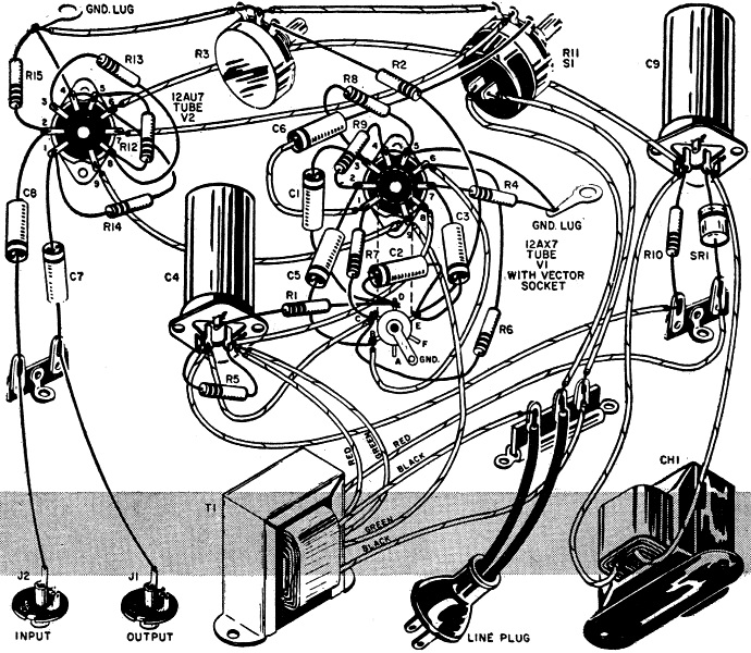
Construction. Layout and wiring are not especially critical.
For convenience a turret socket was used to mount the oscillator tube, V1, and its
components, but a standard socket and tie points will do as well.
Miniature coaxial jacks, of the type found on most hi-fi amplifiers, were used
at J1 and J2 for the output and input connections, respectively. If your setup requires
something different, any conventional type of jack may be employed.
Keep the power supply components well separated from the oscillator and modulator
components, to prevent hum pickup - and orient the tube sockets for reasonably short
lead connections. Make sure that the 6.3-volt heater leads are dressed snugly against
the chassis and that they are well separated from grid terminals and leads.
A miniature amplifier foundation (Bud No. CA-1754) was used for a chassis (any
other setup of suitable size can be substituted). The Bud chassis measures 5" x
7" X 2", and its over-all height with the grille cover in place is 6". The finish
is black crackle - but if some other color appeals to you, it's a simple matter
to go over the chassis with a couple of coats of plastic spray.

Vibrator Circuit Point-to-Point Wiring Diagram.
Parts List
CI, C2, C3, C5-0.05-µfd., 200-volt, metalized paper capacitor
C4a/C4b-20/20-µfd., 150-volt, dual electrolytic capacitor
C6, C7, C8-0.02-µfd., 200-volt, paper capacitor
C9a/C9b-40/40-µfd., 250-volt, dual electrolytic capacitor
CH1-3.5-henry, 50-ma. filter choke
J1, J2-Miniature phono jack
R1 R4, R7, R8, R10-220,000-ohm, 1/2-watt resistor
R2, R6-100,000-ohm, 1/2-watt resistor
R3-500,000-ohm potentiometer (Rate control)
R5-10,000-ohm, 1/2-watt resistor
R9-3.9-megohm, 1/2-watt resistor
R11-500,000-ohm potentiometer (Depth control)
R12-27,000-ohm, 1/2-watt resistor
R13-560-ohm. 1/2-watt resistor
R14-47,000-ohm, 1/2-watt resistor
R15-470,000-ohm, 1/2-watt resistor
S1-S.p.s.t. switch (on Depth control)
SRI-20-ma., 130-volt selenium rectifier
T1-Miniature power transformer, 125 volts at 15 ma., 6.3 volts at 0.6 amp. (Stancor
PS-8415)
V1-Type 12AX7 tube
V2-Type 12AU7A tube
1-Miniature amplifier foundation chassis or equivalent (see text)
1-Turret-type miniature 9-pin tube socket
1-Miniature 9-pin tube socket
Misc. hardware, grommets, tie points, etc.
In some instances, it may be possible to mount the vibrato circuit proper on
the same chassis with the musical instrument amplifier. This can be done provided
that there is room, and that the power transformer in the amplifier can supply the
0.6-ampere additional filament current demanded by the two vibrato circuit tubes.
The plate voltage requirement is approximately 175 volts.
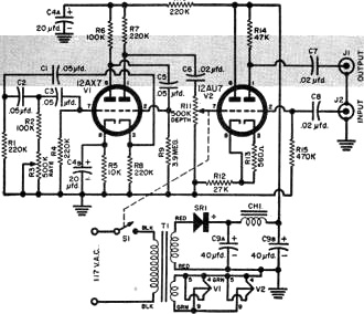
Vibrato Circuit Schematic
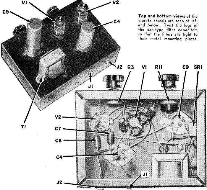
Top and bottom views of the vibrato chassis are seen at left
and below. Twist the lugs of the can-type filter capacitors so that the filters
are tight to their metal mounting plates.
Schematic and pictorial at left show the simplicity of the vibrato construction.
If your amplifier tends to "thump" at vibrato frequency, try a lower value capacitor
for C7.
Block diagram shows correct interconnection of the three basic
components of the revised setup. Use shielded microphone cable between units to
prevent electrostatic hum pickup. If there seems to be excessive 60-cycle hum present,
try reversing line plug of either amplifier or vibrato unit.

Vibrato Circuit Chassis Assembly Photo
Hooking It Up. The vibrato is intended to be inserted or connected
between the musical instrument and its amplifier. All you have to do to use it is
unplug your musical instrument from its amplifier and plug it into the input jack
of the vibrato. Then connect a jumper cable of convenient length between the output
jack of the vibrato and the input jack of the amplifier.
The Rate control determines the rate or frequency of the vibrato effect. i.e.,
the speed at which the rise and fall in amplitude occurs. Proper setting of this
control depends upon the type of instrument with which the vibrato is used and the
type of music being played. Component values given in the parts list permit the
unit to be adjusted over the most useful range of speeds.
How It Works
The schematic shows that the vibrato consists of two parts: (1) a very low frequency
audio oscillator, and (2) a modulator. The low-frequency oscillator is of the phase-shift
type which uses resistors and capacitors C1, C2, C3, R1, R2 plus R3, and R4 in three
RC sections to obtain feedback in the proper phase to produce oscillations. The
rate or speed of the vibrato, i.e., the frequency of the oscillator, is determined
by the resistance and the capacitance used in the RC sections. Thus, R3 is the Rate
or speed control of the vibrato.
V1's second triode section serves a dual purpose: (1) it provides a low source
impedance for the RC feedback loop (taken from the cathode), and (2) it acts as
a buffer to isolate the oscillator from the connection to the modulator (taken from
the plate).
The low-frequency oscillator signal is fed through the gain or Depth control,
R11, to the control grid of one section of the twin-triode modulator, V2. At the
same time, the output signal from the musical instrument is fed through to the control
grid of the second section. The two signals mix in V2, with the result that the
gain or amplification of the musical signal is made to increase and decrease, smoothly
and periodically, at the rate of the low-frequency oscillations. Output from the
modulator is taken through C7 and coupled to the input of the musical instrument's
conventional amplifier.
Plate current demand is very small, so a miniature power transformer, T1, and
a miniature selenium rectifier. SR1, more than meet the requirement.
The Depth or vibrato-frequency gain control determines the amplitude of the vibrato
effect. The more this control is advanced, the more pronounced the vibrato effect
becomes. Proper setting depends upon the strength of the musical signal fed to the
modulator as well as on the type of instrument and the selection being played.*
Probably the best method is to adjust the Rate and Depth controls for the most
pleasing effect. You can get some idea as to proper settings by listening to recordings
in which a vibrato is used. Many beginners tend to use too much vibrato, or to use
it too frequently. Much can be learned by listening to professionals.
Possible Troubles and Cures
No Vibrato Effect: Check all wiring for errors. Make sure input
and output plugs are making good contact in the jacks. Look for faulty components.
Check the tubes. Make sure the 12AX7 tube is in the oscillator socket, the 12AU7
in the modulator socket, and not vice-versa. Check interconnecting cables for a
poor solder joint or broken wire.
Distortion: Most, if not all, vibratos cause a certain amount
of distortion. However, the effect should not be objectionable. Reduce the setting
of the Depth control slightly to see if it improves the condition. If so, check
the musical signal voltage at the input to the modulator. An input greater than
0.7 volt r.m.s. may cause distortion. Check the value of components around the modulator.
Look for a possible defective component. And check the modulator tube.
Thumping in Speaker: A thumping noise at the vibrato rate may
be due to low frequencies pulling the voice coil or cone out of linearity. This
isn't likely to happen unless you have an amplifier with exceptionally heavy bass
response. A high-pass filter cutting off at about 100 cycles inserted between the
vibrato and the amplifier may be necessary in such cases if all else fails.
Hum: Hum can come from a variety of sources such as a poor layout
of components, excessively long leads or poor lead dress, a defective modulator
tube, faulty filter choke or capacitors, unshielded interconnecting cables or cables
with the shield ungrounded to chassis, using the unit close to power wiring carrying
heavy a.c. currents, etc. All of these possible troubles can be easily corrected.
* Maximum musical signal voltage should not be greater than
approximately 0.7 volt, to prevent overloading the unit. Optimum operation occurs
with a musical signal input from the contact microphone between 0.5 and 0.7 volt.
Posted June 13, 2022
(updated from original post on
1/1/2012)
|