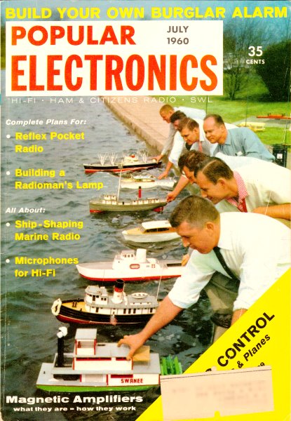
Carl & Jerry: Tussle with a Tachometer
|
|||||||
This is a great example of how Popular Electronics and John T. Frye used the "Carl & Jerry" series to teach some basic electronics design principles through story telling. The same is true with his long-running "Mac's Service Shop" series of techno-dramas. In this adventure, the the two teenagers decide to build a tachometer from schematics they found in a magazine. They debate amongst themselves how the circuits works, the best way to assemble the circuit, component selection, vibration-tolerant mounting, and how to properly calibrate the tach to accurately display engine revolutions per minute (RPM). Being set in 1960, this is one of the first appearances of transistors in circuits rather than vacuum tubes. Transistors were still very mysterious - and even detested - by many electronics hobbyists and professionals, so pieces like this helped the newfangled technology gain acceptance. Carl & Jerry: Tussle with a Tachometer
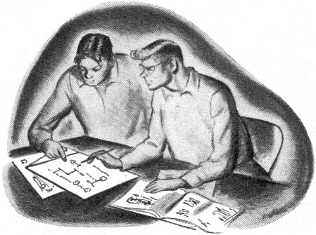
"Here are two electronic tachometers we can build for our car," Jerry said as he spread a magazine and a little yellow booklet on the bench in front of his pal, Carl. "This one uses an 884 thyratron powered by a vibrator power supply. As you can see, it's a detailed construction article, and the gadget uses a relatively inexpensive 1-ma. meter as an indicator. "The other one, in this booklet published by Sylvania, has two 2N233 transistors connected in a one-shot multivibrator circuit. Power is taken directly from either a six- or twelve-volt car battery. However, about all we have to go on here is the diagram and a very limited description. And this tachometer uses a fairly expensive and delicate 50-μa. meter." "Do both work on the same principle?" "Actually, yes. Whenever a selected spark plug fires, the thyratron is triggered into firing or the multi vibrator circuit into flip-flopping. Each 'firing' or 'flip-flop' sends a pulse of current through the meter which has a large capacitor connected across it. This meter-capacitor combination responds to the average current produced by the pulses. Since these pulses are equal in amplitude and are uniformly spaced, the average current indicated by the meter goes up in linear fashion with the frequency of the pulses. That means the meter can be calibrated to show the rpm of the motor." "I say we build the transistor job," Carl decided, as he finished looking over the two articles. "We have the transistors and the meter, and we should know enough about electronics not to need step-by-step in-structions." "Okay, but before we start, suppose you tell me once more why we need a tachometer. Remember we resolved that anything we put on the car had to be functional." "A tachometer is functional," Carl insisted. "Knowing exactly how fast the motor is turning over is important in many cases. For instance, take 'boxwork,' as we hoity-toity motorists call gear-shifting. There is one proper engine speed for each shift, and working with a tachometer permits you to find and use those speeds. Also, we can log the oil pressure for a particular engine speed and use that as a reference later to see if we're losing pressure. We can note at what engine speed our generator begins to charge the battery and use this as a check on the generator's operation. With a little math that takes into account the rear-axle ratio and the rear-wheel circumference, we can convert rpm into mph and check on the accuracy of our speedometer." "Enough!" Jerry interrupted. "I'm convinced. All that bothers me now is how we're going to calibrate the tachometer." "Well, just remember that a particular cylinder of a four-cycle engine fires only once every two revolutions," Carl pointed out. "When the engine is turning over at 4000 rpm, our tachometer will be receiving 2000 pulses per minute."
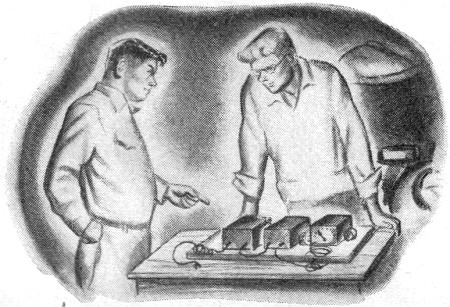
"I've got it!" Jerry suddenly interrupted. "Let's get busy and build the thing. Then I'll show you an easy way to calibrate it." It didn't take the boys long to collect the parts they needed. But Carl and Jerry prided themselves on making their electronic equipment as compact and well-arranged as possible, so they spent considerable time on layout. Since they realized that the tachometer would be subjected to intense vibration in the car, they anchored all parts for the multivibrator circuit solidly on a small perforated board of insulated material, and then fastened this board securely inside a small metal cabinet. Two 10,000-volt capacitors, a neon bulb, and a fixed and variable resistor for attenuating and limiting the high-voltage pulses from the spark plug were similarly mounted in another metal box. Phono jacks on the boxes allowed them to be connected together by a short piece of RG-58/U coaxial cable. Another length of cable connected the multivibrator unit to the meter, which was shock-mounted on a bracket designed to clamp on the steering column. "Well," Carl said as he surveyed the completed tachometer, "I guess we're ready to mount it in the car and calibrate it." "We calibrate it first and then mount it in the car," Jerry corrected him. "Trot out the sine- and square-wave generator and connect it to the input of the multivibrator circuit while I set up the 'scope." Carl did as instructed, then watched as Jerry ran leads from the output of the audio generator to the vertical input terminals of the oscilloscope and connected the 60-cycle test voltage terminal on the 'scope to the ungrounded horizontal input terminal. "Here's my idea - double-check me and see if I'm wrong," Jerry said. "Our 0-50 μa. meter will indicate 0 - 5000 rpm. That means 48 μa. must correspond to 4800 rpm. This reading should be produced when the multi vibrator is receiving 2400 pulses per minute, or 40 pulses per second. "Our square-wave generator should put out a pulse that will trigger the multivibrator in the same fashion that the attenuated pulse from a spark plug does," he continued. "All we have to do is adjust the calibrating resistor of the tachometer so that the meter reads 48 μa. when the multivibrator is being fed a square-wave signal of 40 cps. We can double-check the linearity with square waves of 30 and 20 cps. They should produce readings of 3600 and 2400 rpm respectively." "Sounds okay to me," Carl agreed, "but how are you going to be sure you have exactly 40 cycles from the generator? The dial calibration is reasonably accurate, but you can't depend on it down to the cycle." "That's where the 'scope comes in. We'll compare the 40-, 30-, and 20-cycle output of the generator with the 60-cycle line frequency with Lissajous figures. Watch."
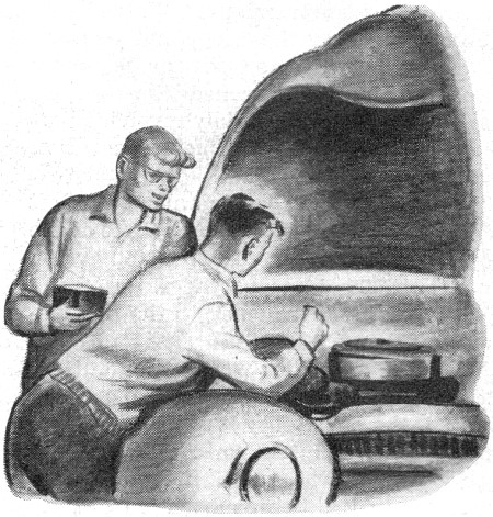
Jerry turned on the 'scope and switched on the audio generator, set for sine-wave output. As he approached the 40-cycle mark on the dial, the rapidly revolving pattern of interlaced curving lines slowed down and finally stopped. "See," Jerry said; "a line along the left side of the pattern would touch three of the loops while a line across the top would touch two. That means the ratio of the signal generator frequency to the line frequency is 2:3 or 40:60." When the generator was putting out exactly 30 cycles, two loops of the pattern touched the imaginary vertical line and only one touched the horizontal line. At 20 cycles, only one loop still touched the horizontal line, but three loops touched the vertical line. Jerry went back to the 40-cycle frequency and switched the generator over to square-wave output. As he did so, the distorted pattern began to wiggle, showing that the change in output had caused the generator frequency to shift slightly. A touch of the generator tuning knob stopped the pattern again. Jerry reduced the generator output until the meter indication began to fall off and move erratically; then he increased the output until the reading was stationary. "Okay, now set the calibrate control for a 48-μa. reading," he instructed Carl. When this was done and the generator set exactly for a 30-cycle output, the meter read 36 μa. When the frequency was reduced to 20 cycles, the reading dropped to 24 μa. "Right on the money!" Jerry gloated as he grinned across at his pal. "The thing is certainly linear over the top half of the scale at any rate. Disconnect that six-volt lantern battery, and let's install the gadget in the car." The multivibrator unit was bolted to the metal body of the car up under the dash, the attenuator unit was mounted on the front of the firewall in the engine compartment, and the connecting coax cable was run through a small hole in the partition. Connections were made to the rear spark plug and to the cold side of the ignition switch so that the tachometer would be switched on with the ignition. When everything was connected, the boys started the motor. Then they adjusted the variable resistor in the attenuator unit until the meter gave a steady and unvarying indication at a constant engine speed, and moved up and down smoothly as the motor was speeded up and slowed down. "Well, it seems to be all right, but I still would like to be sure the indication is accurate at slow speeds," Jerry fretted. "We both know bottom-of-the-scale meter readings are often less dependable than those shown in the top half of the scale."
"Maybe so, but since our square-wave generator won't go below 20 cycles, it looks as though 2400 rpm is the lowest engine speed we know is accurate," Carl observed. "Wait a doggoned minute!" Jerry suddenly exclaimed, clapping an open palm to his forehead. "When the engine is running 400 rpm, the tachometer is receiving 200 shots a minute from a single spark plug. And since all six plugs fire once every two revolutions, the coil is putting out 6 x 200 or 1200 shots a minute, right?" "Right." "And when the tachometer is receiving 1200 pulses per minute, it reads 2400 rpm. Can you see where I'm heading?" "Yeah, I sure can. All we have to do is connect the pickup of the tachometer to the hot lead from the ignition coil and adjust the idle until we get an indication of 2400 rpm. Then we reconnect the pickup to a single spark plug, and if the meter action is linear we should get a reading of 400 rpm." "And 400 rpm is very close to the slowest speed we'll need to read. So if the meter indicates correctly there, we can depend on it over the whole scale." The lead from the coil to the distributor was arranged so that a temporary connection could be made to it. Then Jerry adjusted the idle screw until 2400 rpm was indicated on the meter. Next, he used a pair of plastic photography tongs to transfer the input connection of the tachometer from the high-tension terminal of the coil to a spark plug. "What does it read?" he called to Carl. "It might be just a freckle low," Carl said slowly as he peered closely at the meter, "but it's so close to 4 μa. that you can't tell the difference." "Good!" Jerry said with satisfaction. "We certainly went to a lot of trouble to make sure this thing was telling us the truth," Carl observed, turning off the ignition. "When it comes to test equipment of any kind, either you have confidence in it or it's no good," Jerry remarked. "The time a technician takes to make sure his instruments are accurate is never wasted. Working with a meter whose readings you're not sure of is like using a rubber ruler to build a house. But now I've got the connection back on the spark plug, so what say we taxi around a bit with our tachometer?" "Be my guest!" Carl said, and he opened the car door for his friend.
Posted September 21, 2020 |
|||||||

 Carl & Jerry, by John T. Frye