|
December 1972 Popular Electronics
 Table of Contents Table of Contents
Wax nostalgic about and learn from the history of early electronics. See articles
from
Popular Electronics,
published October 1954 - April 1985. All copyrights are hereby acknowledged.
|
Parts 1 and 2 of this
series covered the theory of nuclear physics and laboratory investigation devices.
This final installation talks about commercially available test instruments for
detecting and measuring nuclear radiation levels. My introduction to Geiger counters
was in the old The Adventures
of Superman television show (the originals with George Reeves) where they
were used by villains to verify that their stash of
Kryptonite
would be sufficient to disable our superhero. I could not find anywhere whether
Kryptonite's emission type is alpha particles (helium nucleus; i.e., 2 protons and
2 neutrons), beta particles (electron), gamma rays (electromagnetic waves), or some
other form. Multiple designs of detectors are used based on radiation type and strength
to be measured.
Side note: Did you know there are various
colors of Kryptonite, all with unique effects on former dwellers
of the planet Krypton?
Parts
1, 2, and
3 of this series appeared in the October, November. and December
1972 issues of Popular Electronics, respectively. See also "Nuclear
Radiation ... Insidious Polluter" in the February 1972 issue.
Part 3: How the Ionization Chamber, Proportional Counter,
and Geiger-Muller Tube Operate

Fig. 1 - Ionization chamber.
By J. G. Ello,
Radiation Measurements and Instrumentation Electronics Division, Argonne National
Laboratory
So far, we have discussed the phenomenon of radioactivity and found that the
three types of radiation are alpha and beta particles and gamma rays. Radiation
can ionize atoms. Since the ions have an electrical charge, they can be directed
in an electrical field to a positively-charged anode (collector) where they are
neutralized by supplying the positive ions with electrons from a battery, thus providing
a measurable current.
To make use of this detector current, a unit of measurement must be established.
Radiological survey meters measure radiation intensity in roentgens per hour (R/hr).
A roentgen is the intensity of gamma radiation that will reduce one electrostatic
unit of ions/cu cm of dry air, or the intensity of radiation that will produce a
little over 2 billion ion pairs/cu cm of dry air. The unit of measurement for detectable
radioactivity is called the roentgen, the order of magnitude most commonly used
is the milliroentgen, or mR.
As an example, a radioactive source is emitting an intensity of 2 mR/hr at a
point a certain distance from the source. If you were to stand at this distance
for one hour, you would receive a 2 mR/hr exposure. If the intensity were only 1
mR/hr and exposure time were extended to two hours, the radiation would be the same
since (1 mR/hr) (2 hr) = 2 mR.
Fig. 2 - Two views of ionization survey meter.
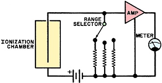
Fig. 3 - Schematic of ionization survey meter.
Ionization Detector
The construction of an ionization chamber
is quite simple. As shown in Fig. 1, it consists of an insulated central anode
enclosed by a shell of conducting material with an alpha window. The ionization
chambers used in many commercial survey meters are designed for only beta/gamma
radiation If alpha particles are to be detected, a very thin window is incorporated
into one end of the detector to allow the particles to pass into the detector. Most
alpha windows are made from 1-mil (0.001") thick Mylar with a coating of conducting
material on both sides. In some ionization survey meters, slide-type alpha and beta
absorbers are used to permit measuring beta particles in the presence of alpha particles
and gamma rays in the presence of beta articles.
An ionization survey meter is shown in Fig, 2. Through use of its built-in absorbers,
it can detect and measure alpha, beta, and gamma radiation. This is a self-contained
unit, powered by internal batteries. It consists of an ionization chamber, range
selector, amplifier, and dc microammeter. The alpha absorber is a 0.01"-thick cellulose
sheet, while the beta absorber is a 0.102"-thick plate of aluminum. Its range may
vary from about 5 mR/hr to 50 R/hr.
A simplified block diagram of the ionization survey meter is shown in Fig. 3.
The ionization detector is maintained at the proper voltage for operation in the
ionization-chamber region of the pulse-size/detector-voltage curve. As ions are
neutralized at the collector, a small ion-chamber current flows through the selected
range resistor. The pulse developed across this resistor is applied to the grid
of the amplifier tube or gate of a field-effect transistor. This minute current
is amplified and passed through the meter movement which is calibrated in mR/hr.
In use, the ionization chamber is located in the bottom forward position of the
instrument with the window on the bottom surface. To detect beta and gamma radiation
simultaneously, the aluminum absorber is pulled up; to detect alpha, beta, and gamma
radiation simultaneously, both absorber tabs are pulled up.
To check the unit's operation, an alpha or beta source is held close to the Mylar
window. With the survey meter adjusted to a suitable range, a reading should be
indicated on the meter. When making surveys, the unit would be moved across the
suspected material at about a 2 in./second scan and close to the material's surface
to obtain a true reading. Whenever a rapid jump of the meter pointer is observed,
radioactivity is most likely present in the material. To determine if it is gamma
radiation, both the alpha and beta absorbers should be in place. To read beta radiation,
the alpha absorber is left in place and the beta absorber is removed. To determine
beta intensity, the gamma reading is subtracted from the new reading. To check for
alpha radiation, both alpha and beta absorbers must be removed. Alpha intensity
is determined by subtracting the reading obtained for beta only from the new reading.
If no change is observed, there is no detectable alpha radiation present.
Proportional Detector
Although the ionization detector is ideal
for detecting the three types of radiation, it needs a very sensitive electrometer
tube or field-effect transistor amplifier stage. To eliminate the need for sensitive
amplifiers, detectors in which internal amplification takes place have been devised.
This amplification is referred to as the proportional region on the pulse-size /
detector-voltage curve. In this region, it is possible to differentiate between
alpha-, beta-, and gamma-generated pulses.
The internal amplification within the detector is caused by increasing the detector
voltage and, hence, the electrical field between the anode and cathode which causes
the electrons produced in the primary ionization of the atom to travel at higher
velocities. The primary electrons also have sufficient energy to dislodge other
electrons in their path and thereby generate larger pulses.
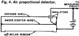
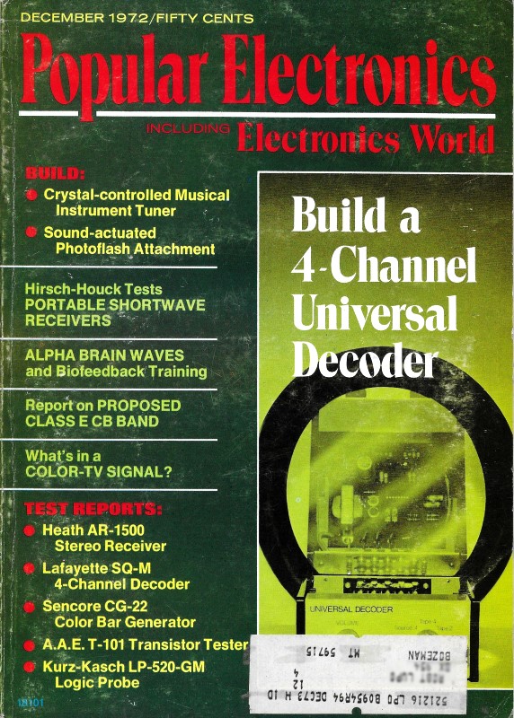
Fig. 4 - Air proportional detector.

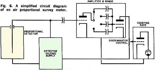
Fig. 5 - An air proportional survey meter.
Shown in Fig. 4 is a basic sketch of an air proportional detector. It consists
of a 1-mil diameter center anode wire mounted on Teflon insulators. The alpha particle
window, fastened to the shell by an adhesive, is made from 0.25-mil thick Mylar.
The detector may consist of one center wire or as many as ten wires.
A battery-operated count-rate survey meter and its air proportional detector
are shown in Fig. 5. The detector has a metal screen to protect the alpha window
against punctures. It is called air proportional because it contains air instead
of a counting gas like that used in Geiger-Muller detectors. The detector is capable
of responding to all three types of radiation and, through the use of a discriminating
control, identify pulses produced by alpha particles and those produced by beta
particles.
The survey meter consists of an adjustable detector, high-voltage power supply,
range selector, amplifiers, discriminator, and count-rate circuit which supplies
current to the dc microammeter. The meter is calibrated in counts/minute instead
of mR/hr as in the ionization and Geiger-Muller survey meters.
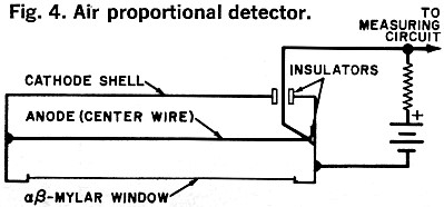
The simplified block diagram of the survey meter is shown in Fig. 6. The
detector is set to operate in the proportional region by means of the detector voltage
supply. Pulses produced at the center wire (anode) are coupled to the grid of the
first amplifier stage and are then coupled to the second amplifier through the range
selector circuit. At the discriminator control, pulses of proper size are selected
and fed to the count rate circuit which supplies the dc current for the meter.
The average efficiency of an air proportional detector is about 10-15 percent;
the detector, therefore, is affected by only 10-15 percent of the total disintegration
taking place. For example, if a radioactive source disintegrates at a rate of 1000
disintegrations/minute (d/min), the detector "sees" about 100-150 d/min.
The surveying technique is the same as for ionization survey meters. The proportional
survey meter is used mainly in the field for alpha detection and measuring. If beta
and/or gamma radiation are to be measured, the discriminator control must be adjusted
to pass the smaller pulses they produce. In addition to gamma pulses, beta and alpha
pulses, if present, will also be indicated under these conditions. Hence, the unwanted
reading (in this case, the alpha reading) must be subtracted from the total reading.
Absorbers can also be used as in the ionization survey meters.
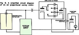
Fig. 6 - A simplified circuit diagram of an air proportional
survey meter.
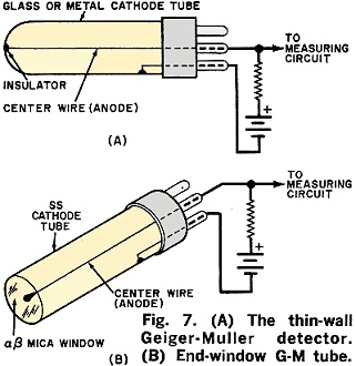
Fig. 7 - (A) The thin-wall Geiger-Muller detector. (B) End-window
G-M tube.
Geiger-Muller Detector
Often referred to as the "G-M tube,"
the Geiger-Muller detector is the most often used radiation detection instrument.
It operates in the Geiger-Muller region of the pulse-size/detector-voltage curve.
The main difference between the proportional detector and the G-M tube is that in
the former, the incident radiation produces an avalanche of electrons at only one
point in the detector, while in the latter, the electron avalanche spreads along
the entire length of the wire anode. The pulse size in the proportional detector
varies with the number of secondary electrons produced. In the G-M tube, electron
amplification is much larger so that the pulse size is practically independent of
the number of electrons produced per nuclear radiation incident. The G-M tube, therefore,
cannot discriminate between types of radiation.
The larger pulse size is due to the high electrical field and the fact that the
G-M tube is filled with a counting gas, such as neon plus halogen, instead of air.
This provides an additional electron amplification factor, referred to as "gas amplification."
The main advantage of gas amplification is that the detector itself requires less
external amplification.
Shown in Fig. 7 A is a basic thin-wall G-M tube, while Fig. 7B depicts
a basic end-window G-M tube. The cathode is stainless steel or glass tubing with
a conductive coating on the inside.
To detect alpha radiation, the wall of the tube must be very thin. For this application,
the G-M detector is fabricated with a very thin window as shown in Fig. 7B.
The cathode material, usually made from stainless steel, is about 0.003" thick,
mainly for strength. The end window is made from very thin mica. The center wire
is supported only at the base end, while the free end is tipped with a glass bead
to prevent spurious internal discharges.
In Fig. 8 are shown two battery-powered G-M survey meters. The end-window
G-M survey meter is at the left; a thin-wall G-M meter is on the right. Both instruments
contain a high-voltage detector supply, amplifier and trigger stages, and a drive
circuit for the dc microammeter. Like the proportional survey meter, an audio jack
is provided for aural monitoring.
A simplified block diagram of a G-M survey meter is shown in Fig. 9. The
detector is maintained at a fixed voltage to operate in the Geiger-Muller region
of the pulse-size/detector-voltage curve. Due to the detector gas electron amplification,
a pulse amplifier is not required; detector pulses are coupled directly to a two-tube
trigger circuit which modifies the pulse sizes and feeds them to the metering circuit
which is calibrated in mR/hr. The coupling between the trigger tubes serves as the
range selector.
The walls and mica windows of the G-M tube are very thin; so, care must he exercised
to avoid any physical shock to the detector. Unlike an ionization survey meter which
can work if the detector's window is ruptured, G-M detectors become inoperative
if the wall or window is damaged.
Another limitation of G-M detectors is their inability to respond indefinitely
to radiation, which can be done by ionization and air proportional detectors. The
normal life of a G-M tube is about a billion counts, after which efficiency drops
off. Many G-M tubes cease to give any indication and may read zero mR/hr when exposed
to a very high radiation intensity.

Fig. 8 - (Left) End-window and (right) thin-wall Geiger-Muller
survey meters.
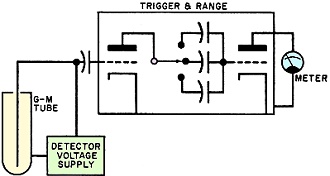
Fig. 9 - Basic diagram of G-M survey meter.
Scintillation Detector
Another type of detector used in surveying
radioactivity is known as the "scintillation detector." It is made from a phosphorescent
material which gives off flashes of light called scintillations, when exposed to
nuclear radiation. Modern scintillation materials are in the form of crystals, liquids,
or gases. The most widely used at the present time is a sodium iodide crystal, optically
coupled to a #6292 photo-multiplier tube.
When exposed to nuclear radiation, the. scintillator gives off a glow which is
converted into electrical pulses by the photo-multiplier tube. The scintillation
detector consists of an optical coupling system contained inside a light-tight package.
To detect alpha and beta particles, the housing must have a very thin opaque window
to exclude all outside light while passing only the radiation particles.
The magnitude of the electrical pulses generated by the scintillations is proportional
to the energy of the radiation. In most cases, the pulse information is analyzed
in a multichannel pulse-light analyzer to identify nuclear radiation by type. In
addition, the scintillation detector can operate in counting ranges many times higher
than the G-M detector.
Solid-State Detector
One of the newer developments in radiation
detection is the solid-state detector. It operates on basically the same principle
as the G-M tube and ionization detector except that it employs a semiconductor material
such as silicon instead of a gas for the counting material. When employed as a detector,
the silicon is in a highly purified state and, like other detectors, is sensitive
to and can measure energy levels of alpha, beta, and gamma radiation.
Silicon diode detectors can be made very small, so small in fact that they can
be mounted in hypodermic needles. Most detectors, however, measure about 1" in diameter
by 1/16" thick. They are used mainly in the health physics field for counting airborne
radioactive particles.
Non-electronic Detectors. Radiological survey meters discussed above are electronic
instruments used for measuring radiation intensity at a given moment in time. There
are, however, devices which measure the total accumulated radiation dosage to which
an object is exposed over a period of time (as short as a few minutes or as much
as a week or more).
The self-indicating dosimeter is basically a miniature ionization chamber made
in the form of a fountain pen. It contains a capacitor which is originally charged
up to a fixed voltage. When exposed to radiation the ions formed in the chamber
remove some of the capacitor's charge and reduce the voltage. The voltage charge
remaining is measured by a movable quartz fiber built into the unit. An internal
scale, when held to the light and viewed through a lens magnifier, indicates this
voltage drop in mR/hr.
Another type of dosimeter employs the radioluminescence phenomenon. Called a
thermoluminescent dosimeter, it works in a manner similar to the scintillation detector.
However, external equipment is needed to "develop" the indicating medium and to
count the accumulated radiation intensity received.
One of the oldest known types of detectors is the film badge. The radiation received
on exposure causes the film to darken in proportion to the amount received. Special
film badges have been developed for low-energy beta, gamma, X-ray, and neutron types
of radiation. Detection of alpha particles is virtually impossible due to the fact
that the film must be packaged in an opaque container. External equipment is needed
for developing and interpreting the film's information.
Posted July 5, 2024
(updated from original post
on 7/20/2017)
|