December 1966 QST
 Table
of Contents Table
of Contents
Wax nostalgic about and learn from the history of early electronics. See articles
from
QST, published December 1915 - present (visit ARRL
for info). All copyrights hereby acknowledged.
|
In 1966, Paul Rockwell wrote a 4-part series for the ARRL's QST magazine
on station design for long distance communications (DX) that covered antenna selection
and siting (Part
I), economics and construction (Part II), Station
Configuration and Receiver Topics (Part III), and
Propagation Quirks and Operating Tips (Part IV). This
the the forth and final installment. One of the handy-dandy items shown is a
Geochron Map-Clock which
had a template of the familiar day-night
analemma-based curve superimposed
on the projection map of the earth. It was quite a deal in its day, and believe
it or not, the company is still in business offering software-based Map-Clocks and
restoring models all the way back to when they first came out in 1965 (only a year
before it appeared here). Of course if you have the $$$, you can buy vintage
Geochrons on eBay.
Part IV - Propagation Quirks and Operating Tips
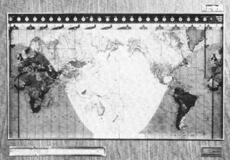
The Geochron Map-Clock. Hams at first stand transfixed before
this - then steal occasional looks. It shows the sun and daylight zones imperceptibly
moving across the Earth, with diurnal and seasonal corrections built in.
By Paul D. Rockwell, W3AFM
Discussion of propagation will be mainly on (a) use of the long path, (b) the
twilight zone, (c) use of meteor bursts for quick identification of weak local signals,
and (d) use of WWV advices.
It is well known among DXers that signals frequently come in better the long
way around the earth. This applies mainly to paths exceeding about 4000 miles the
short way. Under some conditions, the optimum path flips from s.p. (short path)
to l.p. (long path) in a few minutes, and it is difficult to choose optimum propagation.
The neatest station-design to ascertain the better path is that in use at W6AM.
He brings each end of each rhombic, through transmission line, into his shack. By
appropriate relays, the path may be tested or operated on in less than a second
simply by flipping a switch. Similar technique can be (but practically never is)
applied to driven arrays and Yagis.
The question of when, in a longer term, it is desirable to search for long-path
openings, is not easily answered. Recent experience gives the operator his best
competence. However, some general guidance is to look along the twilight zones.
The twilight zone, globally, has an important relation to h.f. propagation. For
example, on the long hauls, about 6,000 to 20,000 miles (s.p. or l.p.), phenomenally
good transmission can be realized for small portions of the day, on paths nearly
parallel with this zone. According to the relation between the maximum useable frequencies
(m.u.f.) and operating frequencies, propagation may be better on the day or night
side, or directly along the twilight zone. Seasonally, the zone runs due N-S at
the equinoxes; mornings NW-SE in summer, NE-SW in winter; evenings NE-SW in summer,
NW-SE in winter. The NE and SW directions are for northern latitudes. Long propagation
paths perpendicular to a single intermediate twilight zone, on the other hand, tend
to be poor, especially when the zone is near mid-path. This is because MUFs are
usually much different in night and day zones - sometimes called the "contrast"
problem. An appreciation of these phenomena is useful in estimating diurnal and
seasonal openings to various parts of the world.23
A chart, from information prepared by Frank Smith, W5VA, is presented as Table
III. Frank has maintained daily schedules for several years over difficult DX paths
- notably with VU2JA, plus 4S7NE as well.
Sometimes signals arrive from unexpected directions - neither s.p. or l.p. Particularly,
arrivals from north and south have been reported for DX signals as much as 60° displaced
in geometric azimuth. Signals reflected from the aurora zone are usually characterized
by a gravelly sound. To a lesser extent, this can be observed on signals propagated
through the aurora. When Europeans are heard working the Far East, it's a good sign
that Far East propagation will be good, later in the day, from the United States.
Some propagation phenomena are useful for preliminary identification of signals
in DX work. One of these phenomena is signal enhancement by reflection from meteor
trails. The enhancements may be 20-to-40 db. in amplitude, and are typically about
one second in duration. Unfortunately they are not always present. When they are,
they serve to distinguish weak nearby (non-DX in the 20-meter skip-zone) signals
from bona fide weak DX. An appreciation of this saves the time of waiting for the
weak station to identify himself by sending his call letters. Another phenomenon,
useful in recognition, is the well-known rounding of keying envelopes by multipath
transmission. That is, keying which has passed through several propagation hops
and has arrived by a combination of several paths, is likely to sound softer (in
the sense of less clicky) than ground-wave or single-hop propagation signals.
It is conservative of one's time in general listening, to spend more time in
good conditions than bad. WWV sends propagation advices every five minutes. While
these are for the North Atlantic only, their extremes are indicative of conditions
in general. A few minutes at "N7" payoff better than an hour at "W4." At W3AFM,
a receiver is kept on WWV. A digital clock permits turning this receiver on a second
or two before the announcement. Thus the check-up takes only about ten seconds.
An automatic timer could be installed. City power runs typically ± 3 seconds
of accuracy.
To be guided wholly by NBS-CRPL dicta, however, can (a) subtract the fascination
of the completely unexpected, and (b) cause loss of country contacts. On rare occasions,
a choice DX find will turn up on an otherwise dead band. Sometimes these signals
last only a few minutes, and are heard by only one or two W stations, within a hundred-mile
distance of each other.
Operation and Subjective Elements
Time and keen operating practices can be traded off, to some extent, for station
technical-effectiveness. Especially in this era of well-equipped DXpeditions, it
is more important to be active on the right frequency at the right time, than to
have the ultimate in DX e.r.p. Thus, a station at home, a home within 20 minutes
drive of the place of work, and a job that doesn't require being out of town on
trips, can add more to the countries total (if that's your criterion of performance)
than a 200-foot tower and 50-foot boom.
A mountain-top summer-cottage, well sited and well equipped, may be the answer
(a) for contest or weekend DXing, (b) if there are motivations to get the hobby
out of the home, or (c) if the home location is DX-wise impossible. Remote control
of the country sites is not out of the question - but is seldom put to practice,
because of the costs and difficulties. W6YY u.h.f.-remotes transmitters etc. at
Mt. Wilson, elevation 5710 ft., from his home at La Canada, California!
Neighborhood relations and station esthetic appearance are often problems. Even
if it would fit on the home lot, a hundred-foot lattice tower and fifty-foot boom
may be out of the question. In cities, the type of antenna beyond which troubles
are likely to develop with neighbors is often something like a 45-foot telescoped-pipe
self-supporting mast, with a 25-foot boom lightweight Yagi. Such a practical compromise,
however, will not compete in contests, no matter how good the operator, against
a fully equipped, well-sited station. The latter, of course, usually has a good
operator along with it.
Flag-poles, if of interest for good-looking mast construction, are made by John
Lingo and Son, Inc., P. O. Box 1237, Camden, New Jersey. Pneumatically telescoping
masts are marketed by Andrew Corp, P. O. Box 807, Chicago, Ill. 60642. Costs of
the latter range from $2,000 to $8,000 for heights of 30 to 100 feet.
Table III W5VA's LP/5P DX Chart
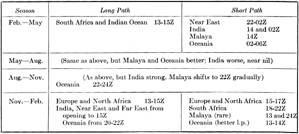
Notes:
1. East Coast subtract 1 hour: West Coast add 1 hour to times above.
2. Months may be read February 15, etc. for W5 land; February 1, etc. for northern
U. S. latitudes.
3. 4th Quarter l.p. sigs under South Pole reach W5 1 hour earlier than W8/1/2/3;
sigs over North Pole 1 hour later.
4. November-February 01-02Z; India and Gus/Asia l.p.; FB8XX 589SP - Band sounds
dead, actually is not.
Operating Tips
Much has been written on operating practices for DX effectiveness. Listening
is far more productive than calling CQ. In this connection, the tradeoffs represented
by Figure 6 are recommended over the more conventional ones of Figure 7. (Part II,
October QST).
It is better to listen several times a day for short periods, than to listen
for the same total time in one session. In tuning, as from 14,000 to 14,100 kc.
repeatedly, it is slightly preferable to "snap back" (as is done by oscilloscope
horizontal sweep circuits) than to tune uniformly back and forth. In contests, it
is preferable to tune from high to low, as "the pack" predominantly moves the other
way. In pile-ups, a short call precisely timed and on the right frequency, can be
more effective than a longer call at higher power.
Logging, filing, and QSL procedures cannot be neglected. DX intelligence ("G-2")
is very important. DX-alert nets are good. But when they are not available, it,
is sometimes possible to exchange alerting services over telephone landlines. Particularly
useful are DXers who have retired from full-time employment and spend several hours
a day scanning the bands. Having tools, test gear and spares close at hand can be
a practical advantage in the event of breakdown at a critical time - some wrong
Sunday afternoon.
Zeroing Capability
It is desirable to be capable of zeroing-in with an accuracy better than 100
c.p.s. on top of the station communicating with the desired DX station. This can
be accomplished most quickly by the use of a very sharp receiving filter (say, 200
c.p.s.). It is very helpful if a second receiver can be employed to permit the zeroing
operation to be performed without detuning the desired DX station, which may be
very weak and fading into and out of the noise. It is especially convenient if the
second-receiver v.f.o. can be cross-coupled, transceiver style, to the exciter,
so that the transmit frequency automatically follows that of the zeroing receiver.
A problem that plagues some exciters is that the spotting zero is different from
the key-down zero. Such a situation can seriously impair DX effectiveness.
Receiver frequency calibration should have accuracy of ± 1 kc. or better
over the 14,000 - 14,100-kc. range. This is to permit prompt action on DX news-bulletin
or other DX tips.
 Break-in Capability Break-in Capability
Full break-in is a very desirable feature. Use of even the best available t.r.
electronic switches may degrade station DX performance materially. This is because
the noise figure, at best, is inferior to that of a good receiver. However, these
devices are sufficiently good to be useful during transmissions. A way of avoiding
degradation during the most critical listening periods is to bypass the t.r. switch
automatically when the transmitter is switched off. Figure 8 (blocks 3, 4 and 5)
in Part III, November QST, illustrates the interconnections and components. The
B & W Model 381 has proved satisfactory at W3AFM; it permits full c.w. break-in
by signals S6 or better. With it, one can tell while sending the approximate level
of clutter on the calling frequency.
Shaping of Keying Characteristic
It is well-known that the corners of the r.f. envelopes of keyed characters should
be rounded to prevent clicks. For intelligibility, the leading corner should be
less rounded than the final corner. What is less well-known is that a considerable
improvement (as much as 3 db. in effective output-power) may be built in the forward
part of each character without loss of the rounded-corner. This is done by use of
a very high value of filter capacitor in the high-voltage power supply. At W3AFM,
120 μf. are used. It should be noted that, in the case of linear amplifiers,
output is not a direct function of plate voltage as in the case of Class C grid-driven
amplifiers. For grounded-grid amplifiers the gain is nearly always constant (below
saturation) at 10-13 db. (output power 10-20 times input power). Thus, to use this
technique effectively, the driving stage and conceivably its driving stage should
also be provided with high-capacitance filters. The technique should also be useful
for handling modulation peaks. It has no value unless, as is usually the case, the
h.v. power-supply regulation is imperfect.
Station Clock
The station clock should always run on GMT, and logs should be kept that way.
Digital 24-hour types, such as the Tymeter Numechron, are preferable to round-face
clocks. The map-clock, made by Geochron, is an interesting and useful guide to propagation
and is a hobby in itself. It shows automatically the sun's position, daytime and
nighttime zones, and corrects for seasonal changes.
Size is about 3 feet wide by 2 feet high by 4 1/2 inches thick. A Mercator transparency
moves imperceptibly, according to time of day, across a red dot at the middle of
the map, representing the sun's zenith position. The red dot moves even more slowly,
±23 1/2° in latitude and a few degrees in longitude, forming annually a thin
figure of eight (the analemma), Most impressive, the precise daylight and nighttime
zones are continually displayed. The clocks are made by Geochron, 2515 Palms Place,
San Mateo, California, 94401
In preparing this series, lots of helpful correspondence developed in connection
with sending out preliminary draft texts and accumulating information. My special
thanks to W1WHS, K2HLB, W2GhK, W2JT, W2PCJ, W2VCZ, K3OKX, K3TVU, W3BMX, W3GRF, W4AO,
W4BPD, W4FFV, W4KFC, W4YHD, W5VA, W6AM, W6SAI, W8BRA, W9HHA and KH6DVD.
Author's Sequel
Not all that was in my head got onto paper. Not all of what did get on paper
is clear. Also, a couple of errors are worth correcting.
Transmitters should be at least be mentioned in a tract like this. Essentially
all top DX stations in W/K land use kw. finals. About half these are home-built,
It may help those who plan home construction of this kind, to relate a point-of-view
developed from experience. This is, that it pays to buy components of first quality
right from the start. For example: Westinghouse Oz-Paks, Ebert mercury power relays,
B & W Type 800 chokes and Linemaster 632-S foot-switches are fine products now
in use at W3AFM but each was preceded by a cheaper one. The predecessors now are
in a junk box ... a total loss. Cheaper does not mean more economical.
Referring to Part I, Sep., on antenna siting. There are three zones under consideration,
namely: 1. Near-zone (I2R losses) under the antenna, 2. The reflection
zone, 3. The far-zone (horizon clearance). Take a site such as W3CRA's on Fig. 2.
Frank Lucas has perhaps the strongest signals coming out of W/K land. His near-zone
I2R loss is negligible; he uses a balanced horizontal radiator and a
reasonable antenna height of λ/2. His take-off lobe is formed within the
first fraction of a mile, on a nearly ideal sloping forezone. This low-angle lobe
is able to clear the horizon because of his high altitude in reference to surrounding
terrain. If the antenna were situated back over the ledge of the hill on a level
plateau, so that the antenna could not see the sloping foreground, then his take-off
angle would be only that determined by the height of the antenna over the plateau.
Some questions have been raised about the curved coordinates in Fig. 2.
This is 4/3 earth-radius paper. On it, radio rays passing through the refraction
of standard atmosphere are straight lines. To construct such paper, draw a level
straight line. From the center of this line mark off distances in miles. Then drop
down for various heights according to the formula:
dmi = 1.4 √(dft)
The opening remarks of Part III were mostly intended for Table I rather than
Table II. Table I appears in Part I, September.
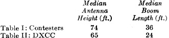
Contesters are more heavily equipped than DXCCers.
In Part III, 75A4 mod (4) refers to the r.f. stage.
23 - Persons interested in h.f. propagation should acquire and study an excellent
value in this field: Ionospheric Radio Propagation (NBS CRPL), 1965, From Supt.
of Documents, USGPO, Washington, D. C. 20402, $2.75. See also "Simplified CRPL DX
Predictions," QST, July 1957, p. 28.
Posted October 25, 2021
(updated from original post on 5/27/2014)
|


