|
|||||||||||||
 |
|||||||||||||
WWV Moves to Colorado - Part I |
|||||||||||||
This is the first of a two-part series on the move of the WWV transmitter stations operated by the National Bureau of Standards (now called National Institute of Standards and Technology) from Greenbelt, Maryland, to Boulder, Colorado. WWV Part II appeared in the February 1967 edition of the ARRL's QST magazine. WWV began transmitting time / frequency standards in 1920 in order to provide a means for remote stations and laboratories to calibrate local standards that would prevent transmitting stations from interfering with each other. Although most people don't realize it, the 60 kHz signal that their 'atomic' clocks and watches use to self-adjust time emanates from the WWVB antenna in Boulder. This first installment of the article discusses the history and rationale for relocating the WWV facility to a new location. The second part gets into the technical aspects of the WWV facility's equipment and operation. As usual, I am amazed at the pioneers who conceived of, designed, and implemented these kinds of operations. Here are Part I and Part II, and this is a short story on WWVB I wrote. See also "Standard Frequency Broadcast Service of NBS," June 1945 Radio News. WWV Moves to Colorado In Two Parts: - Part I By Yardley Beers, W0EXS
Peter Viezbicke W0NXB, chief engineer for design and construction of the new station (left), and Leo Honea W A3ADB, ex-KH6MG, engineer-in-charge of WWV, stand in doorway of new transmitter building. The inscription "WWV" in the background was brought from the Greenbelt building to Fort Collins.
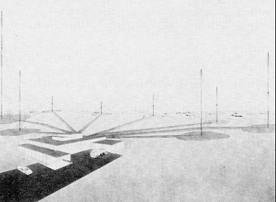
Artist's rendition of WWV building and the eight antenna masts which form an arc an the ridge east of the building. To the left is the 200·ft. high 2.5-MHz. dipole antenna and to the right the 100·ft. high 5.0-MHz. dipole. Between them are the dipoles for the 2.5-, 10.0-, 15.0-, and 20-MHz. signals. In the left and right foreground are the two 88·foot standby wide-band monopole antennas.
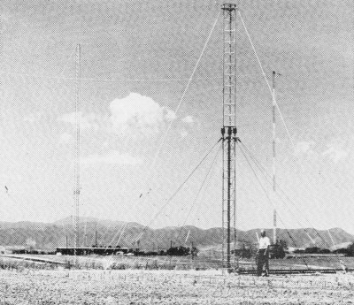
A view of the 20- and 2.5-MHz dipole antennas.
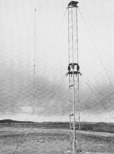
One of the monopole standby antennas and one of the dipole single-bond antennas. The striped tower in the background is one of the four supporting the WWVL main antenna. The building is the WWVB-WWVL Transmitter Building before the addition of the new wing. At 0000 GMT on December 1, 1966, the veteran standard time and frequency station WWV at Greenbelt, Maryland, closed down forever, and at essentially the same instant a new station with the same call letters and services came on the air from Fort Collins, Colorado. The event was commemorated for amateurs and short-wave listeners by the availability of a special QSL for those who reported hearing the new station in its first hours of operation, as announced earlier.1 There were several reasons for the construction of the new station and for the move. In the first place, the old station was obsolescent, and maintenance was a serious problem. The difficulty of maintenance was aggravated because the station, in addition to providing a continuous service, had always had some experimental aspects to its program, and there had been frequent innovations and modifications to the equipment. Unfortunately, inadequate records of cable connections had been kept, and long ago the staff members who made them departed for retirement or for other employment. Nowadays good record are being kept so that this particular difficulty should not return. At any rate, for many years the station was kept on the air with a remarkable degree of continuity through the conscientiousness and ingenuity of the staff in the presence of serious obstacles. In contrast, the new station, employing the latest transmitter designs, provides much more efficient operation. In addition, there is much greater flexibility, since the transmitters are comprised of identical units - except that some of the transmitters, being higher powered than the others, contain one more amplifier stage -which can be tuned to any frequency. In the old station only a few of the eight transmitters were identical. Unlike the old transmitters, in the new ones modulation is applied at low levels, and all subsequent stages are accurately linear. In this way there is available a wide choice of modulation types: a.m. or single sideband, with either sideband, and with any arbitrary degree of carrier suppression that may be desired. Thus, the new transmitters contain the same design features which are generally considered desirable modern amateur transmitters. The wide flexibility of modulation is particularly advantageous with respect to coordination with WWVH in Hawaii, which uses the same carrier frequencies. This station, also obsolescent, is expected to be rebuilt a few years hence. In this event, similar features will be incorporated. Then the upper sideband can be used by one station and the lower by the other, and users who wish to distinguish between the two stations will be able to do so much easier than at present. A survey made by the organization which was then known as the Central Radio Propagation Laboratory of NBS (now the Institute for Telecommunication Sciences and Aeronomy of ESSA) in Boulder indicated that the signal strength coverage would be better or just as good from the new site - except, of course, for the small area in the vicinity of Washington, D. C., which has been served by ground-wave propagation. The area which should be aided notably by the relocation will be the West Coast of the U. S. A. Here the propagation time delays of signals from WWV and WWVH were nearly equal, and it was difficult to separate the time pulses. Also, reception frequently was marred by fading, resulting from the fact that the signal strengths were usually nearly equal. With the relocation, this region is pushed out into the Pacific Ocean, where there are few users. Finally, there is the advantage of administrative efficiency. WWV is now located on the same site as two other NBS standard-frequency and time stations, WWVB (60 kHz.) and WWVL (20 kHz.). Therefore, there can be some reduction in staff since all of the transmitters can be monitored from a single point, and the staff of one station can assist or fill in at the other in case of emergency. Furthermore, communication lines with the parent organization responsible for the administration of these stations, the Radio Standards Laboratory of the National Bureau of Standards in Boulder, Colorado, are greatly simplified. Also, it is easier to synchronize the station with the NBS Atomic Standards, which are located in Boulder. When the Greenbelt station was established, the property was under the jurisdiction of the U. S. Department of Agriculture. The radiation of standard-frequency signals did not disturb agricultural experiments that were conducted in adjacent fields. However, in time, jurisdiction passed to NASA, who constructed the laboratories of the Goddard Space Center adjacent to the transmitter site. When NASA was confronted with the problem of trying to conduct experiments under conditions where a few inches of unshielded wire would give a sizeable deflection on an oscilloscope, their management requested that when NBS replaced its obsolete transmitters they be relocated at some more remote point. This situation also encouraged the move to Fort Collins. Before the final decision to rebuild and relocate WWV was made, permission was obtained to allow a special voice announcement to be made over it for one month in the summer of 1964. In it, listeners were requested to write in. The some 4,600 who did were sent a rather lengthy questionnaire, and about 3,500 of these were returned filled out. About one-quarter of the respondents were representatives of organizations. These statements in themselves indicate the need for the station. It is interesting to note that 35 percent of the respondents were licensed radio amateurs, confirming the interest of amateurs in the station. The detailed answers provided guidance in determining which of the services should be retained and which should be changed and how. They also provided assurance that the specific needs of the Washington ground-wave high-accuracy area would be met largely by other existing services. It might be noted that 10 MHz. was the most widely used carrier frequency and 25 MHz. was the least. Layout of the Fort Collins Site The new site is located about seven miles north of the City of Fort Collins on Colorado Route No.1, and is about an equal distance to the east of the first foothills of the Rocky Mountains. The land is nearly flat. The soil has a high alkali content and a high electrical conductivity. Portions of three small lakes are contained within the area of the site. The most conspicuous feature is the group of nine 400-foot towers which supports the WWVB-WWVL main and standby antennas. The building housing those transmitters is amongst these towers. These antennas are essentially top-loaded verticals with arrays of horizontal wires forming capacitive hats and with the bottom ends of the vertical radiators terminating in "helix houses" (actually two stories tall) containing loading coils. The ground conductivity has been improved by burying a network of wires.
If there were Nielsen ratings for the non-broadcast services, WWV would no doubt
top the list - perennially. Now, after forty years in the Washington, D. C., area,
the station has been moved to the West. Here is an overall description of the new
facilities at Fort Collins, Colo.
The new WWV station was financed by a Congressional appropriation of $970,000. The largest expenditure has been for the transmitters. However, a considerable portion has been used in constructing the new building and in adding a new wing to the old building. The new building is one story high and is located in a depression in the terrain so that its roof is approximately level with the ground of the area to the north, where the WWV antennas are located. Thus, the building should cause no shadows in the antenna patterns. In the main portion of the new building, there are located eight transmitters along an area adjacent to three of the outside walls. The area adjacent to the fourth outside wall, the front, contains the main entrance and offices. The center of the building contains a laboratory and shielded enclosures for housing the frequency-control equipment. Wings of the building contain a workshop, a garage, and a diesel-powered generator for emergency power. Commercial electric power is supplied by underground cables from two different sources. The building is thoroughly air-conditioned, since dust was a major maintenance problem at the old station at Greenbelt, and it is recognized that potentially the problem is likely to be worse at the new location on open prairie. The addition to the old building contains some offices for administration of the whole site and such much-needed amenities as a conference room and a small kitchen. The road system is such that visitors come first to the old building, and hence these central facilities are located here. Incidentally, visitors who make advance arrangements through either the Boulder or Fort Collins offices are most welcome. In such cases we can be sure to have someone on hand to receive them. However, unannounced visitors are to be discouraged, as the staff is small and often there is no one who can leave his duties to receive them. 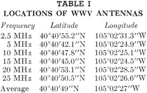 Table 1 - Locations of WWV Antennas The transmitter power levels are slightly increased, but the transmission frequencies at the new station are the same as at the old: 2.5 kw. on 2.5, 20, and 25 MHz., and 10 kw. on 5, 10, and 15 MHz. At both the old and new stations it was considered necessary to have eight transmitters: six in operation and two as standby. In the old WWV there was a schedule for the rotation of transmitters so that in turn each transmitter was taken out of action for a while for cleaning and other maintenance, the switchover taking place during one of the scheduled silent periods so that the transmission schedule was uninterrupted. Also, at the old WWV the antennas were fed by open-wire lines which were switched between transmitters. However, at the new WWV in Fort Collins, antennas are fed by rigid coaxial line, and each one is connected permanently to a single transmitter, the layout being such that no two coaxial lines cross. Altogether there are eight antennas at the site. Six are half-wave modified "sleeve" vertical dipoles, one for each of the above frequencies. The remaining two are broadband h.f. monopole antennas for the two standby transmitters. These eight are located approximately at equal intervals on a semicircle, with the two wide-band standby antennas at the opposite ends of the semicircle, and the others placed in such a way to make interaction a minimum, The exact locations are given in Table I. The half-wave vertical antennas, with heights compensated for end effects, employ standard commercial tower sections and are designed to withstand winds up to 112 m.p.h. The antennas are center-fed with rigid coaxial cable and are mounted on hinged bases fastened to concrete foundations. The upper one-quarter wavelength section, supported on insulators from the lower one quarter wavelength section, constitutes the upper half of the radiating system. The sleeve consists of nine equally-spaced quarter-wave-long wires connected from the center of the tower (one-quarter wavelength above ground) that slope downwards to the ground at an angle of 45 degrees. This sloping skirt, each wire appropriately insulated from ground, not only functions as the lower half of the radiating system, but also serves to guy the antenna. With this design the driving point impedance is approximately equal to the 50-ohm coaxial line, and the current developed at the junction of the base and ground plane is minimized. This permits connecting the coaxial shield and the tower base directly to ground. In addition, tests made on the antenna indicated that a radial ground screen did not make any detectable change in the input impedance; thus it was not incorporated into the system. This design, readily adaptable to a coaxial feed line, provides low angle omnidirectional radiation and yields a gain of approximately 1.7 db. over its one-quarter-wavelength monopole counterpart. By employing a double-stub adjustable tuner, it can be matched precisely to 50 ohms. Finally, with the shorted stubs connected into the feed line at the antenna base, each is at d.c. ground potential, thus protecting the transmitters from possible lightning damage. The wideband standby antennas, also fed by 50-ohm rigid coaxial line, are series-excited, base-fed, vertically-polarized, omnidirectional radiators. The antennas operate over a radial ground screen and cover a frequency range of 2.5 to 25 MHz.2 The antennas are capable of handling 50 kw. of power with a nominal standing wave ratio of less than 2.5 to 1 when connected to a 50-ohm line. Continuous coverage is accomplished without switching. 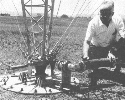 Hugh Stewart, Information Officer, views the base of one of the broad-band monopole standby antennas. The eight transmitters contain bandswitching units which are identical except for the obvious difference that four of them have high-powered amplifiers. Thus, although the single-band antennas cannot be switched between transmitters in case of breakdowns units may be interchanged. As stated earlier, modulation is introduced at very low levels, and s.s.b. or a.m. may be used with any degree of carrier suppression which may be desired. Provision is included even for applying different modulations on the two sidebands, although there is no contemplation of the use of this feature in the near future. The s.s.b. generator uses a crystal filter at 5 MHz., and provision is made for synthesizing all oscillator frequencies from the local cesium atomic standards. A great deal of attention has been paid to obtaining frequencies of high spectral purity. The modulation is controlled by an elaborate device called" the time code generator-programmer", and two spares are on hand in case of breakdown. This device, in conjunction with an announcing machine and two code keyers, provides the complete WWV audio modulation program. Such features of the program as propagation forecasts, geoalerts, and UT2 corrections3 are readily changed as necessary by manual switches on the announcing machine or by replacing code wheels on the keyers. The bulk of the transmitters is composed of linear amplifiers, which are standard commercial stock items, identical with some which are in wide use by military, commercial, and amateur stations. However, because of the severe requirements for reliability with twenty-four hour daily operation, the power amplifiers are derated to fifty percent of their normal levels: for example, the amplifiers which are used at 10 kw. output are ones which in standard commercial service would be rated at 20 kw. (Such derating had also been in practice at the old station.) The building layout is such that the power of each transmitter can be raised from its present level by the addition of at least one more stage, should it be desired at a later time. Participation of Amateurs The engineers in charge of all three stations are amateurs: Leo Honea WA3ADB, ex-KH6MG (WWV); Richard F. Carle K0LYM (WVVB-WWVL); and Sadami Katahara KH6DK (WWVH). Also, the engineer in charge of the design and construction of the new WWV is an amateur: Peter P. Viezbicke W0NXB. Other amateurs on the staff of the stations are John A. Duffield K0KHZ, Howard E. Michel, Jr. K0BPY, and George Tam KH6EM. Amateurs participating in other parts of the NBS Time and Frequency Program include: Miss Kay Barclay K0BTV, Don Halford W0JVD, Don Hilliard W0EYE, Edward Rogers K0GKB, J. E. Gray, W0GNV, and the author. (Part II, describing the frequency-controlling equipment, will appear in a subsequent issue.) * Chief, Radio Standards Physics Division, National Bureau of Standards, Boulder, Colorado 80302. 1 QST, November, 1966, page 53. 2 This antenna was described in detail in November 1966 QST (Pappenfus, "The Conical Monopole Antenna"). -Editor. 3 Information on these services is contained in NBS Miscellaneous Publication 236, ". BS Standard Frequency and Time Services," 1966 edition; for sale by the Superintendent of Documents. U. S. Government Printing Office, Washington, D. C. 20102, price 15 cents.
Posted June 15, 2020 |
|||||||||||||
 |
|||||||||||||
|
|||||||||||||
 Table
of Contents
Table
of Contents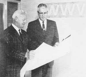

|
||||||||||||||||||||||||||||||||||||


