|
February 1947 Radio-Craft
 [Table of Contents] [Table of Contents]
Wax nostalgic about and learn from the history of early electronics.
See articles from Radio-Craft,
published 1929 - 1953. All copyrights are hereby acknowledged.
|
Here in the February 1947 issue
of Radio-Craft magazine is part three of a six-part series on Antenna
Principles. The first two parts concentrated on dipole antennas and feeders, and
multi-element long-line and rhombic antennas. Part three is on directional
arrays and radiation fields. In addition to a bit of theory, real-world examples
are given of various directional antenna configurations along with field
strength graphs. Without powerful computers to calculate and plot out predicted
radiation patterns, a large combination of experience and in-situ measurements
was required. A huge amount of time was spent for even relatively simple arrays.
Finitely detailed topographical and structural models are now available which,
along with very precise electromagnetic field calculation algorithms allows
efficient and accurate planning for complex systems like the world's cellular
networks.
Part II of
this "Antenna Principles" series appeared in the January 1947 issue,
Part III in
February, Part IV in March,
Part V
in April, and Part VI in the May 1947. I do not yet have Part I from the December 1946
issue.
Antenna Principles Part III - Directional Arrays and Radiation Fields
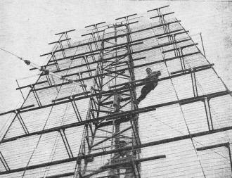
Photo A - Example of a complex FM array, the antenna of WOR's
station in New York City.
By I. Queen
Previous articles described the operation of simple antenna systems suitable
for broadcast reception and amateur operation.
More elaborate designs are used for commercial communication and broadcast transmission.
All practical antenna systems and arrays are directional to some extent. They
may be grouped in accordance with their characteristics as follows:
1. Those designed to receive or transmit along one or a few narrow beams only.
In other directions the system is relatively ineffective.
2. Those producing an irregular pattern.
3. Arrays having circular patterns in the horizontal plane. Actually these types
are directional with little propagation upward or downward, but they are commonly
termed nondirectional.
Beam Arrays
For point-to-point communication there are many advantages in using an antenna
which concentrates power in desired directions only. Secrecy is maintained and very
high efficiency is possible. Interference with and from other transmissions is reduced
to a minimum. Sharp beams become practical at the higher frequencies because. the
radiating systems can be constructed within a reasonable area.
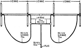
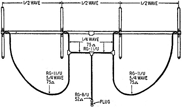
Fig. 1 - This array consists of four dipoles operating in phase.
The Amphenol broadside array is an example of a well-designed communications
antenna for the 152-162 mc band. These frequencies are assigned to fire departments,
police, press, and railroads. The same array also can be used (with slightly lower
efficiency) in the neighboring amateur and government bands which extend from 144-198
mc. Its excellent directional characteristics recommend it for fixed or mobile point-to-point
service.
The electrical design of the Amphenol broadside array is illustrated in Fig.
1. Four half-wave dipoles are spaced by one-half wavelength and fed at their centers.
The feeder system from the array may use RG8U or (for very long lines) RG17U co-axial
cable.
The large-diameter tubing lowers the inductance and raises the capacitance of
each dipole. The low Q broadens the response curve and accounts for the very wide
band over which the antenna is effective. Use of low-impedance cable eliminates
difficulty with voltage loops and leakage. Note that the outer dipoles are fed through
cables which are one full wavelength longer than the cables which feed the inner
ones. Therefore each dipole is fed in phase.
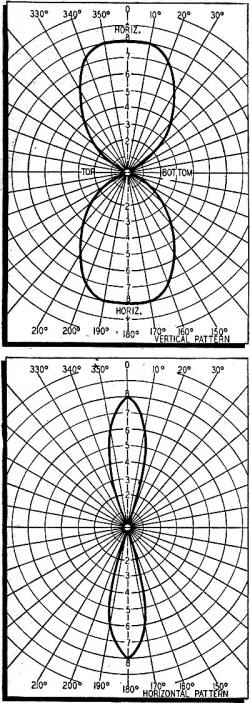
Figs. 2-a and 2-b. Patterns of Fig. 1 antenna. Hold page on side
to better understand 2-b.
Power is propagated only broadside to the array. Assume that a wave starts out
at some instant from one dipole. It reaches the next dipole one-half cycle later
because of the half-wave spacing. At this later instant the second dipole tends
to radiate a field which is out of phase with that which has jus t reached it from
the other. The two opposite fields cancel out along either direction of the
array.
A receiving antenna located broadside to the array intercepts equal power from
each of the four dipoles since in this case all currents are in phase, The total
gain in the second case is 7 db over that of a single radiator.
The narrow fields which are possible with the broadside array are shown in Figs.
2-a and 2-b. The first is a cross-sectional view as it might be seen by an observer
standing on a level with the array (if radio waves were visible). Little power is
lost through upward propagation. The second figure is a view looking down on the
antenna.
A sharper beam can be transmitted by using a still more complex array. Photo
A shows such a system. This particular antenna is erected above the forty-third
story of the building which houses WOR's FM station WBAM, more than 500 feet above
street level in the heart of New York City. It has an effective gain of 60!
This array is beamed toward Washington, D. C., and can be used for transmitting
at 47.1 or 106.5 mc. The interesting antenna is of the same type as that which warned
its GI attendant of the oncoming Japanese attack on Pearl Harbor. It is also similar
to the array used in 1946 to contact the moon by radar.
Irregular Patterns
To properly serve two or more populated centers and to avoid possible interference
with nearby transmitters, it is often necessary to design a broadcast antenna so
that it radiates an irregular field pattern (Fig. 3). This also makes it possible
to reduce power which otherwise might be wasted on mountains, lakes, and wooded
sections. An irregular field pattern requires the use of more than one antenna tower.
The pattern can be varied by adjusting the magnitude and phase of each tower current
and the position of each tower.
Because of the many variables concerned, direct mathematical calculations become
quite involved and consume a great deal of time. Several instruments are available
for easing the problem, however. At least one mechanical device* has been designed
for antenna calculations.
A still more modern and convenient instrument is the RCA Antennalyzer†.
An oscilloscope is used to give instantly the field pattern which results from the
use of up to five antenna towers. Sixteen dials control the Antennalyzer, four for
each tower. Since one tower is taken as the reference, it requires no control. The
four dials represent: magnitude and phase of the tower current; distance and angle
(in azimuth) of the tower, with respect to the reference tower. To operate this
instrument, the desired pattern is drawn with chalk on the face of the oscilloscope
tube. Then the dials are manipulated until the same pattern is traced by the electron
beam. The necessary tower factors are taken from the dials.

Fig. 3 - Field pattern of WMAL, Washington.
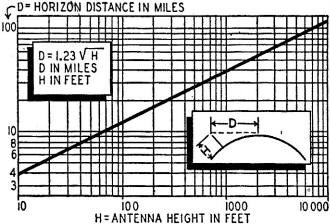
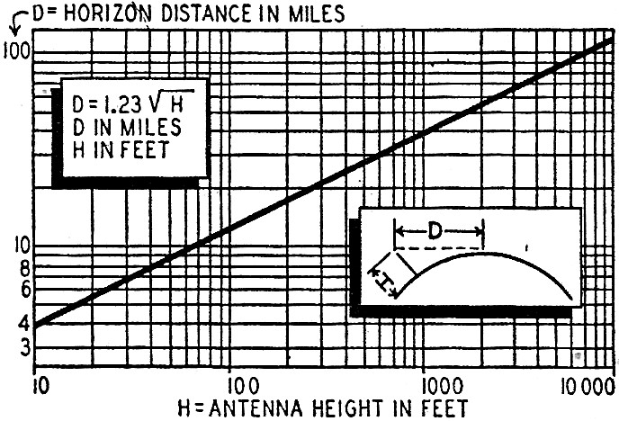
Fig. 4 - Antenna height and broadcasting range.

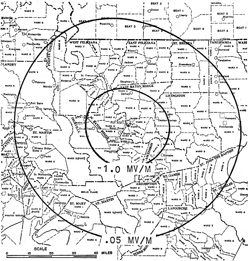
Fig. 5 - A typical radio contour map, showing 1,000 and 500
microvolt per meter coverage.
Nondirectional Radiation
Many large and small manufacturers are doing research in the design of high-frequency
broadcast antenna systems because of the widespread and increasing importance of
FM and television.
Requirements for high-frequency broadcasting present very special problems. First
there is the consideration of distance coverage (Fig. 4). Because of the line-of-sight
limit, large population centers can be properly served only by locating the transmitting
antenna in the heart of a city and high enough so that it overlooks most obstructions.
FM, television, and multiple communication require very wide modulation-frequency
bands, and consequently special antenna designs. As the carrier frequency increases,
the length of a resonant conductor becomes smaller, and as the modulation band increases,
the cross section must be made greater.
Many high-frequency antenna systems now in operation take on odd shapes and sizes,
often named for the objects they resemble (cloverleaf, turnstile, rocket). Each
is designed for circular radiation at low angles, a wide modulation band, and small
mounting area.
All these commercial antennas are designed according to the fundamental principles
already set forth. They have, however, many interesting special features, arising
in most cases out of using different methods of solving the same problem. A description
of these antennas is worth an article in itself, and the next number in this series
will cover a number of them.
Field Surveys
By mathematical calculations and by the use of precision mechanical computing
devices and such instruments as the Antennalyzer, it is possible to determine accurately
the field radiated by any antenna. However, the actual field intensity at any point
is known only when ideal conditions exist. Especially at the higher frequencies,
field strength and contour are determined not only by the radiation characteristics
but also by the height of the antenna and the obstructions.
Broadcast stations must supply actual field measurements to the FCC so that possible
interference between stations can be eliminated and maximum population coverage
provided.
The Federal Communications Commission requires the use of accurate receiving
and continuous recording equipment for the survey. Generally the chart may be driven
by the same mechanism which actuates the speedometer of the automobile or truck
which holds the equipment. Recording is made along eight radials extending from
the transmitter, each spaced by about 45 degrees. Highways spaced so conveniently
do not generally exist, but it is usually possible to choose streets or roads which
run approximately parallel to such radials.
The survey must continue past the points which indicate 1,000 microvolts per
meter of field strength so that the required 1,000-microvolt contour may be drawn.
A 500-microvolt contour around the station is required also, but due to difficulty
with fading at such low field strength it is usually computed from the data for
the stronger field, A typical recording is shown in Fig. 5.
* Radio-Craft, August 1943, p.652.
† Radio-Craft, May, 1946, p.536.
Posted November 23, 2020
|