|
April 1947 Radio-Craft
 [Table of Contents] [Table of Contents]
Wax nostalgic about and learn from the history of early electronics.
See articles from Radio-Craft,
published 1929 - 1953. All copyrights are hereby acknowledged.
|
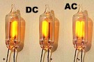
Note with DC only the positive electrode glows, whereas with
AC both electrodes glow. (Wikipedia)
Most people who have been in
the electronics world for a while know that
neon light bulbs* used to be commonly
employed as a "pert-near" voltage regulator reference of between 55 and 65
volts, depending on the type. The familiar NE-2 has a turn-on voltage of 65 Vac
(90 Vdc), for instance, and the voltage across the terminals remains there
with little change regardless of the current through the bulb - a lot like a
Zener diode. Neon bulbs are also used as non-invasive RF power detectors. Most
people probably do not know, however, that incandescent bulbs also have
properties that make them useful for purposes other than just lighting up a dark
space. Incandescent light bulbs have been used successfully for voltage
regulation and RF power measurement. They have also been used as dummy loads for
transmitters. John Parchman details some of these uses in a 1947 issue of
Radio-Craft magazine.
* See "Let's Use Neon Bulbs"
in the July 1953 issue of QST magazine.
Lamp Bulb Resistors
By John B. Parchman
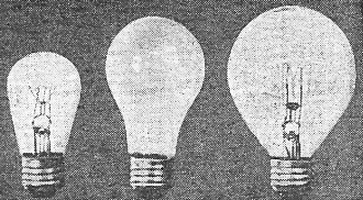
Just a few of the many lamp types available.
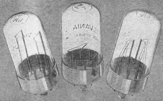
One filament in these power measurement lamps carries r.f.; the
other, easily measured a.c. (Photos courtesy Sylvania Electric Product). [Here
is a page for the Sylvania PM8 tube]
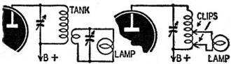
Fig. 1 - Lamps used in dummy antenna circuits.
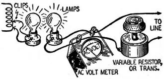
Fig. 2 - Setup for comparison measurements.
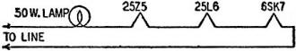
Fig. 3 - Lamp used as a high wattage resistor.
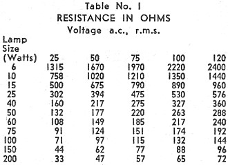
Table 1 - Resistance in Ohms.
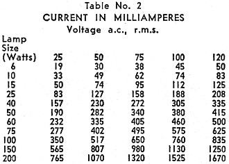
Table 2 - Current in Milliamperes.
Most radio men consider the incandescent lamp bulb a lowly thing useful only
when it gets dark. Actually, the lowly lamp bulb can be used for many things around
the radio or electric shop, such as for resistances, continuity checks, dummy antennas,
and voltage or current measurement.
Most radio or electrical men have used test lamps which incorporate a lamp bulb
to locate blown fuses or to check the presence of voltage in convenience outlets,
and as indicating devices, etc. How many ever used one to check the presence of
line voltage at the set? Many sets are dead simply because of a faulty line cord
or plug which is discovered in many cases only after the switch and most of the
tubes (in a series string) or the switch and transformer have been checked for continuity.
One of the greatest objections to the lamp bulbs for such uses have always been
that the resistance of an incandescent filament-type lamp varies over a considerable
range according to the amount of current passing through it. This property can be
used to advantage in some applications. The tungsten filament in lamps is an excellent
regulating filament. It is not as good as nichrome wire and some of the more complex
alloy wires used in automatic ballast regulating tubes because the resistance does
not remain constant for large variations of current. But when the resistances of
the lamps are known (see the tables in this article), this characteristic is not
serious in many applications. The voltage regulation for a given current range can
be obtained from the tables. Curves can be plotted by the reader on suitable graph
paper from the data given in these tables. Such curves were not included in this
article because of space limitations and the difficulty of reproducing the curves
in sufficient detail for accurate use.
R.F. Power Measurement
Among the common uses of light bulbs in the radio field is as dummy antennas
or for measuring a transmitter's power output. The law requires some form of dummy
antenna to minimize unnecessary interference. One of the cheapest methods is to
use incandescent lamp bulbs coupled to the plate tank coil by means of a pickup
coil or clipped directly across a few turns of the tank coil. The higher the resistance
of the lamp (the lower the wattage), the greater the number of turns required for
coupling. The coupling should be varied until the greatest brilliancy is obtained
for a given power input. At frequencies below 15 or 20 megacycles, the lamp is practically
a resistance load. At frequencies above 30 megacycles, reactance of the leads, etc.,
introduces loss of power. To eliminate as much loss as possible, leads should be
soldered to the terminals of the lamp instead of using a socket. Some losses
may be eliminated by making the lamp load resonant with a variable condenser (see
Fig. 1). Other circuits are given in various handbooks and texts.
A lamp which would light up to approximately normal brilliancy at the apparatus
power input value should be chosen.
Measurement by Comparison
When more accurate check methods are not available, the brilliancy of the lamp
connected to the apparatus under test may be compared with the brilliancy of a similar
lamp connected to a known source of supply such as the 115-volt line (see Fig. 2).
A closer comparison can be made if a colored filter is used to view the lamps. If
no such filter is available, one can be made by holding a piece of glass over a
smoky flame. Care should be taken to secure an even deposit on the glass. The deposit
of soot or carbon black collected on the glass serves as a light filter. When viewed
through such a filter, the brilliancy of the two lamps can be readily compared.
They are made to match by varying the voltage supplied to the standard lamp.
A variable source of voltage can be obtained by using resistance in series with
the lamp or with an autotransformer or Variac.
The voltage supplied to the standard lamp can be easily determined, after the
brilliancy has been matched, with a common a.c. voltmeter, which can be found on
most radio benches.
From the tables given in this article, you can find the current passing through
the lamp and the resistance at the measured voltage. By the simple application of
Ohm's law you can now determine the power output of the device. For example, let's
consider that a voltage of 100 volts a.c. r.m.s. was measured across a 100 watt
lamp bulb. This corresponds to 760 milliamperes and a resistance of 132 ohms. Ohm's
law, when applied to alternating currents and voltages in a purely resistive load,
is the same as for d.c. Therefore, the power output would be: power = volts times
amperes or 100 x 0.760 = 76 watts.
If resistances or dissipation ratings desired cannot be found in the tables,
arrangements in series, parallel, or series-parallel can be worked out to give almost
any value.
Currents in circuits can also be measured with incandescent lamps when a suitable
milliammeter or ammeter is not available. The lamps are connected in series with
the load and the same procedure as outlined for determining power is used. The
voltage drop across the lamps is measured and the value of current can be determined
from the tables. For instance, with a voltage of 25 across a 200-watt lamp, the
current from the tables would be 765 milliampere.
This technique can also be used to determine voltages in the absence of an a.c.
voltmeter. Of course, it is necessary to calibrate the source of supply voltage
for the standard lamp before beginning testing. In this case, the brilliance of
the lamps is matched and the voltage read from the calibrated supply used for the
standard lamp
Possibly one of the oldest uses for incandescent lamps is as an inexpensive means
of obtaining voltage drops. For example, we have a piece of apparatus which uses
three tubes and desire to operate it from the regular power source with a series
resistor or ballast lamp. The tubes naturally should be selected to have the same
current rating, 300 milliamperes, 150 milliamperes, etc. For the sake of illustration,
suppose a 25L6, 25Z5, and a 6SK7 tube were to be operated from a 115-volt a.c. supply.
These tubes all draw 300 ma of filament current and have a combined voltage drop
of 56. Therefore, a drop of 59 or 60 volts at 300 ma must be obtained in a dropping
resistor. By referring to curves drawn from the data given in the tables, it is
found that a 50 watt lamp would give a resistance of 204 ohms and a current of 295
ma for a voltage drop of 60 (Fig. 3).
For accurate measurement of power output, current, and voltage, a series of power
measurement devices are available on the market. Examples of these are the power
measurement lamps made by Sylvania Electric (Radio Craft, March, 1944). These lamps
are designated PM3, PM4, PM5, PM6, PM7, PM8, and PM9. They have two filaments in
one bulb and operate on the principle (brilliance comparison) described in this
article. Their resistance ranges from 36 ohms to 310 ohms. Their power ranges from
0.005 to 25 watts at frequencies from 15 to several hundred megacycles. Their voltage
drops range from 0.5 to 55.
Posted May 26, 2020
|