|
January 1951 Radio-Electronics
 [Table of Contents] [Table of Contents]
Wax nostalgic about and learn from the history of early electronics.
See articles from Radio-Electronics,
published 1930-1988. All copyrights hereby acknowledged.
|
We've all heard of
a Van de Graaff
(Robert J.) electrostatic generator, but have you heard of a
Wommelsdorf (Heinrich) generator (aka influence machine)? I hadn't prior
to reading this article entitled "Electric Space Ships" from a 1951 issue of
Radio-Electronics magazine. It took careful reading to get my head
around the propulsion scheme detailed by Professor Hermann. At first I thought
he was describing electric propulsion, but in fact his machine uses electrical
energy generated from the sun to accelerate some form of liquid propellant via
static electric charges. Therefore, this is not a system capable of indefinitely
sustaining itself and its payload (which includes human inhabitants). In fact,
the good professor proposes a geostationary refueling station above the Earth's
equator which can be used to facilitate interplanetary exploration. It is a
very interesting concept, but history shows the idea never got off the ground
- so to speak. Here is
Electric
Space Ships Part 1.
Electric Space Ships: Part II - Using the sun's energy
By Professor Hermann Oberth
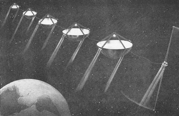
The author's concept of a string of the electric spaceships on a flight through
outer space. Because there is no gravity, the saucer-like ships can be made
extremely light by earthly standards, although they cannot land on a planet.
In this second article of this series we shall discuss the details of a spaceship
and its power plant - the energy source being the sun's rays. A large mirror
concentrates solar heat on a specially constructed boiler. The vapor produced
by the boiler drives a turbine, and the turbine in turn drives a special electric
generator which provides both the propelling force and control for the ship.
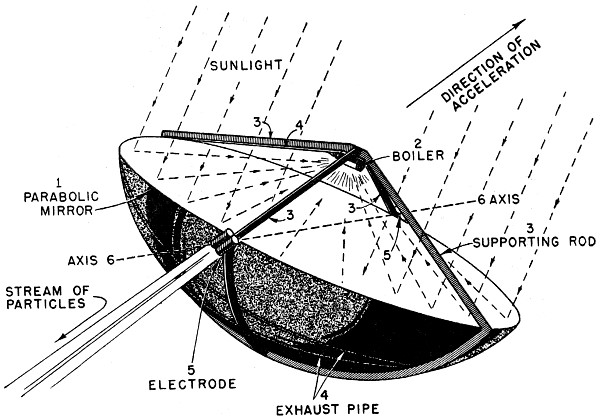
The parabolic mirror 1 (see Fig. 1) reflects the sunlight on the boiler 2
which drives the dynamo. (Whether this should be a dynamo or an influence machine
of the Wommelsdorf type depends on the behavior of the electrodes in outer space,
a factor which cannot yet be predicted. My present feeling is that the Wommelsdorf
machine is most suitable.)
The side of the boiler toward the mirror has a dark surface, while the side
away from the mirror has a reflecting surface to reduce heat loss. The elements
marked 3 are supporting rods. Like the mirror, these can be very lightly built
(by earthly standards) because of the extraordinarily slight acceleration.

Fig. 1 - Drawing showing the essential parts of the solar-powered
spaceship.
An exhaust pipe 4 leads the vapor in a spiral to the shady side of the mirror
where the vapor condenses. Another pipe leads the condensed vapor back to the
boiler. (I purposely avoid using the terms water and steam because other liquids
are better suited for this machine.)
The two electrode couples are marked 5, and are of the type described in
the first article. These can be rotated about axis 6. Since the mirror itself
can be rotated about its own axis and the direction of this axis is that of
the sun's rays, the recoil can be made to work in any direction in space. With
the couples in the position shown, acceleration takes place in the direction
of the arrow.
The slight acceleration which the recoil imparts to the apparatus is not
enough to separate the vapor and the liquid from each other, and even this slight
acceleration is available only after the boiler begins to function. Furthermore,
the liquid can collect on the side facing the mirror only when the acceleration
is toward the sun; otherwise the empty wall would be heated.
A Rotating Boiler
We can overcome this difficulty as well as gain other constructional advantages
by allowing the entire cylindrical boiler to rotate about its own axis. Fig.
2 is a sketch of the boiler. Here 1 is the boiler and 2 is the working liquid
which, because of the rapid rotation, collects on the boiler walls. The vapor
collects in the middle of the boiler and flows to the turbine 3, which I have
taken to be a two-stage machine. The guide vanes of the turbine are rigidly
connected to the boiler wall.
The vapor then enters pipe 4 which leads it to the shadow of the mirror,
where it is condensed, and the liquid returns through pipe 5. From 5 the liquid
enters funnel 6 which is rigidly attached to the boiler and rotates with it.
Centrifugal force then drives the liquid out of 6 and into the boiler through
the tubes marked 7. Valves to prevent backflow of the liquid are marked 8.
The rotating vanes 10 of the turbine are mounted on shaft 9 which rotates
within the boiler but in the opposite direction. The rotor runs at a hyper-critical
velocity and therefore acts as its own counterbalance.
The source of current, here taken to be a Wommelsdorf machine (an improved
influence machine invented in 1922), is indicated by 13, and 12 is a special
coupling unit. The space within this machine is at the same pressure as the
boiler for better efficiency and simpler construction.
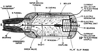
Fig. 2 - A simplified cross-section of the vapor driven
power plant proposed for the spaceship. The entire unit can be sealed against
losses of the vapor.
The construction of the machine would be greatly simplified if the vapor
within the boiler could flow freely in and out through 11, but this is not possible
if water is used as the working fluid. The stator of the current generator 13
rotates in the same direction as the boiler, while the rotor turns with shaft
9. Slip rings are marked 14 and 14', while 15 and 15' are current collectors.
The potential difference between these will be in the order of several thousand
volts, but it is possible to insulate the rings very effectively in gravitationless
space.
In Fig. 2 we also have 16, a casing which contains the whole machine. On
the side toward the mirror is a window 17 which is permeable to both heat and
light, and the rest of 16 is made of reflecting sheet metal. The outside of
the boiler is black. The space between 1 and 16 or 17 is, of course, filled
with vapor at the temperature of the boiler and at the same pressure as the
exhaust vapor at 4.
Completely Sealed
No rotating parts of the machine pierce the outer wall at 4, 5, 16, or 17.
The machine can therefore be effectively sealed off against losses of the working
liquid - a most necessary measure.
In this machine three rotations are possible with respect to shaft 9:
a. Rotation of the shaft and of the rotors;
b. Rotation of the boiler together with the stators;
c. Finally, the casing 16 together with all the other equipment, rods, mirror,
electrodes, etc., can be brought to rotate about the boiler shaft.
In fact, because of the friction in bearings 18 and 19, the boiler must eventually
impart its rotation to the rest of the device, while the turbine rotors 3 and
the rotors of the current generator 13 absorb the opposite momentum.
I have therefore provided for another influence machine 20, whose stator
is rigidly connected with the outer casing 16 while its rotor is similarly fastened
to the shaft of the boiler. Depending on which direction the current flows through
this machine, it will exert a turning moment on 16. Thus it is backed up, so
to speak, on the boiler and accordingly turns the rest of the machine in the
right position.
It would be advantageous to connect several such mirror engines with cables
which, because of the small current, can be quite thin. The artist's drawing
shows a string of such engines. In the foreground, to the right is the shelter
or cabin for the space travelers. Ordinarily they occupy two chambers, connected
by a long cable, which rotate about the common center of gravity. In this way
the illusion of weight arises. Near the center of gravity is a pair of electrodes
which draws its power from the mirror engines through the common cable. One
can also imagine a switch point placed between the two electrodes to connect
the influence machines either in parallel or in series.
Power and Efficiency
We must now say something about the propulsive power and the efficiency of
the electric spaceship.
The machines naturally perform better the stronger the sunlight. For example,
in the vicinity of Venus they could accomplish twice as much as in the neighborhood
of the earth. But of course the exact value of the solar constant outside the
earth's atmosphere is unknown. Since the appropriate measurements are not available,
I would guess it to be about 2.2 gram-calories per square centimeter per minute,
and for our purpose this is close enough. Converted into the corresponding values
for square meters and meter-kilograms per second, the radiation falling on each
square meter is 156 mkg/sec. We can assume that the boiler can use about 30%
of this energy, which might appear to be quite high, but we are justified in
assuming a high operating efficiency here. The influence machine would, in turn,
convert about 95% of this into electrical energy, which, expressed in m-g/sec
per square meter of the mirror surface, comes to
44.5 m-g /secm2.
We can assume that without the fuel the apparatus weighs 400 grams per m2.
This appears to be very small, but because of the slight requirements which
they must meet from a statics point of view, these machines do not need to be
heavier. Naturally one can take as much propellant for such a machine as is
desired.
The first problem which could be solved - which, incidentally could be solved
with liquid propellants only at great, unnecessary expense - would be the construction
of a station circulating about the earth at a distance of 42,100 km (about
25,300 miles) above the center of the earth or 35,700 km (about 21,420 miles)
above its surface at a velocity of 1,723 m/sec (3,850 miles an hour). Such a
station would always hover above the same point on the equator if its orbit
were in the equatorial plane. Otherwise it would describe a figure eight, as
seen from the earth, which would bring it over the same point of the equator
twice a day.
Such a station would be extremely valuable for television as well as for
many other, particularly military, uses.
The next problem for the electric spaceship would be a flight around the
moon.
The electric spaceship could also carry out interplanetary flights, and indeed,
this could be done in several months, whereas it has been estimated that such
voyages would have to be reckoned in terms of years if liquid propellants alone
were used (cf. Hohmann: Die Erreichbarkeit der Himmel-skorper. [The Attainability
of the Celestial Bodies]).
In any case this spaceship could not land on one of the larger celestial
bodies - it is far too weakly constructed for that. For this purpose it would
have to carry a space boat which would be powered with atomic energy or with
liquid propellant, while the spaceship itself circled about the celestial body
like an observer's station without further expenditure of fuel.
Besides these two possibilities - powering the space boat with fuel or with
atomic energy - there is a third, at least for visiting celestial bodies which
have no atmosphere, like the moon.
Corpuscular radiations contain very little matter. At high potentials they
have only a very slight impact force, but they do have a high energy content.
We can also assume that, given high enough velocities, the particles would travel
a great distance in parallel paths.
Equally charged mass-particles repel each other, but currents traveling in
the same direction attract each other. Moving-charged particles are electric
currents. If we can impart a high enough velocity to streams of particles, it
is reasonable to assume that the particles would no longer tend to fly apart.
Of course this will have to be tested first on a station in cosmic space, for
I would not care to extrapolate blindly the results obtained from Geissler tubes
and cyclotron streams to the corpuscular streams from an electric spaceship.
I assume that this would certainly succeed with electron streams, but whether
it would work with positive rays is something I do not care to affirm.
The spaceboat could receive in a Faraday cage the corpuscles streaming toward
it and with this help generate an electric wind whose reaction is sufficient
for landing on Mercury, the moon, or Ceres. Since it is also much lighter than
the spaceship and does not have to carry the latter's machinery with it, its
acceleration can be much greater and its construction heavier and more compact.
Mathematical Analysis
From our estimated solar constant we might expect a kinetic energy of 8.8
to 14.6 mkg/sec m2. If we wish to give the propellant a velocity
of 10 km/sec, then 1 gram of the latter contains kinetic energy equal to 5,100
m/kg. It therefore follows that at a distance of 150 million kilometers from
the sun, energy can be radiated at a rate of 8.8:5100 = 1.7 mgr/sec to 14.6:5,100
= 3 mgr/sec per second per square meter of the mirror surface.
If the electric spaceship carries 2 kg (1 kg = 2.2 lbs.) of matter per square
meter of mirror surface, this would suffice for a period of acceleration of
from 670,000 sec. or 8 days to 1,170,000 sec. or 14 days.
The total increase in velocity would be:

I have added the subscript i to v because the spaceship would attain this
velocity only in gravitationless space. If it started out from a station rotating
about the earth, it would have to exceed the velocity of the station. In so
doing, the original circular orbit (in the sense indicated by the Keplerian
laws of planetary motion) would first have to pass over to an elliptical orbit;
however, the ellipse would not be completed, but in each instant it would develop
into an ever wider ellipse, so long as the machine operates.
Accordingly the spaceship ascends in a spiral path, the differential equation
of which cannot be integrated in a closed expression. And its velocity actually
diminishes in the process at the same time that its total energy, because of
the increment of potential energy, increases. Thus vi indicates only
the so-called ideal velocity. I would also like to point out that of this 17
km/sec only about one-half or 9,000 m/sec can be used for propulsion, while
the remainder must be used to check the velocity in the vicinity of the goal.
The following formulas refer to fuel consumption, increase of velocity, and
the duration of the acceleration:
m = m0 + m' t.
(1)
where m is the mass of the electric spaceship, m0 its initial
mass, t the time. and m' the quantity of fuel or propellant expelled during
each second. Obviously the spaceship expels the same quantity of propellant
in each second, since its distance from the sun does not change so rapidly,
and, to save time, the machines are allowed to run at the highest number of
revolutions per minute so long as they must operate. From (1) and the equation
for velocity increase (see Part I) we obtain the increase in velocity between
the times t1 and t2:
From this we get:

If we substitute m1 for m0 - m' t1 and t
for t2 - t1 we get:

It is obvious that all the energy derived from the source of current will
not be used for the acceleration of the propellant. A large part of it is lost
in the charging processes going on. Moreover, not all the corpuscles fly off
at the same speed, so that here too a certain amount of energy is lost.
It would take us too far afield, and would also be pointless in view of the
uncertainty of the estimates referred to above, to describe exactly how I arrived
at the values used. But I estimate that the kinetic energy of the expelled particles
constitutes about one-fifth to one-third of the electrical energy supplied.
While this may seem a rather low efficiency, it is no problem as we have an
unlimited energy source from the sun.
With an exhaust or repulsion velocity of 20 km/sec, V1 would therefore
be twice as great, i.e., 35,836 m/sec; but from 32 to 56 days would then be
required for the approach and slowing down for landing.
Posted January 19, 2021
|