|
January 1951 Radio-Electronics
 [Table of Contents] [Table of Contents]
Wax nostalgic about and learn from the history of early electronics.
See articles from Radio-Electronics,
published 1930-1988. All copyrights hereby acknowledged.
|
 It takes a while - and money - to accumulate
issues of the vintage electronics magazines for posting articles here on RF Cafe.
Often I can find groups for sale that comprise a full calendar year, but often they
are groups of random months and years. That makes getting a complete series of articles
like this one on "How an Electronic Brain Works" difficult. A lot of times installments
appear every other month, so when a series has more than ten articles, it can run
well over a year. For instance Part I of "How an Electronic Brain Works" appeared
in the September 1950 issue of Radio-Electronics. The final chapter, Part XIII,
appeared in October 1951. Throughout the series, authors
Edmund C. Berkeley and
Robert A. Jensen describe the workings of "Simon," their compact
electronic computer - some even call it the first "desktop computer." Here is an
article (with photos) about "Simon" in the November 1950
Scientific American magazine. It takes a while - and money - to accumulate
issues of the vintage electronics magazines for posting articles here on RF Cafe.
Often I can find groups for sale that comprise a full calendar year, but often they
are groups of random months and years. That makes getting a complete series of articles
like this one on "How an Electronic Brain Works" difficult. A lot of times installments
appear every other month, so when a series has more than ten articles, it can run
well over a year. For instance Part I of "How an Electronic Brain Works" appeared
in the September 1950 issue of Radio-Electronics. The final chapter, Part XIII,
appeared in October 1951. Throughout the series, authors
Edmund C. Berkeley and
Robert A. Jensen describe the workings of "Simon," their compact
electronic computer - some even call it the first "desktop computer." Here is an
article (with photos) about "Simon" in the November 1950
Scientific American magazine.
See Part IV
- Long Division with Relays and
Part IX - Some Electronic
Circuits for Computers.
Part IV - Long division with relays - our little electric brain
learns how to divide and to convert decimal numbers to binary and back again. Simon
is getting an education

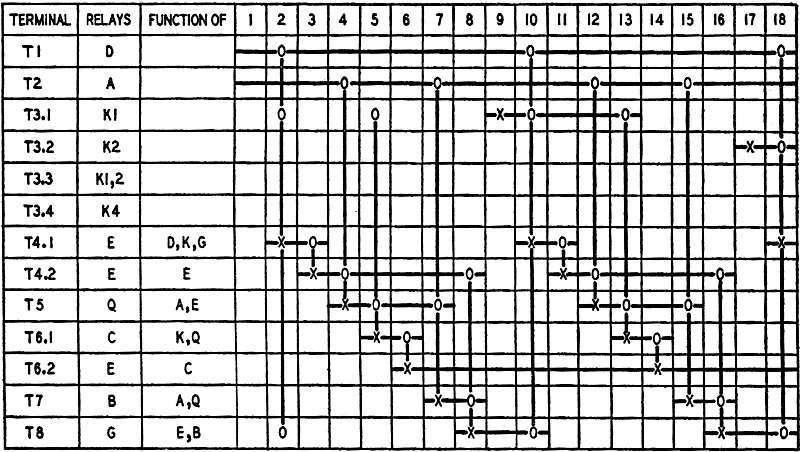
Fig. 1 - Timing chart which shows the sequence of operation for
the first two stages of the division with binary numbers performed by the circuit
of Fig. 1.
By Edmund C. Berkeley* and Robert A. Jensen
Previous articles of this series have shown how an electric brain made of relays
can add, subtract, and multiply.
Now we shall carry out division. As before, we shall consider the process in
binary notation, the scale of two.
As a second topic, we shall consider how to make a relay calculator convert a
number from decimal notation to binary notation, and back again. There is every
reason in the world why the machine itself should convert any decimal number, say
23, into the corresponding binary number (in this case 10111, one-oh-one-one-one,
or one 16 plus no 8's plus one 4 plus one 2 plus one 1).
Addition, subtraction, and multiplication turned out to be very simple in binary
notation as compared with decimal. The same is true with division: binary division
is simple as can be.
Suppose we divide 1101 (one-one-oh-one, or 8 plus 4 plus 1, or 13 in decimal)
into 10000101 (one-oh-oh-oh-oh-one-oh-one, or 128 plus 4 plus 1, or 133.
We do this in the same general way as we do in decimal division, except that
we act as if we knew only the two digits 1 and 0:
Only two multiples of the divisor are used, one times the divisor, and zero times
the divisor - and the latter is of course zero in every digit. No other multiples
of the divisor are needed. If we simply compare the divisor with the partial remainder
at any point in the division, we can tell whether the digit of the quotient is 1
or 0.
Circuits for division
As before, to keep the circuits simple, let us ignore a number of fine points,
such as: fractions; the binal point (the analogue in the scale of two of the decimal
point in the scale of ten); positive and negative numbers; size of numbers; etc.
Suppose that we have an eight binary digit dividend, and a four binary digit divisor.
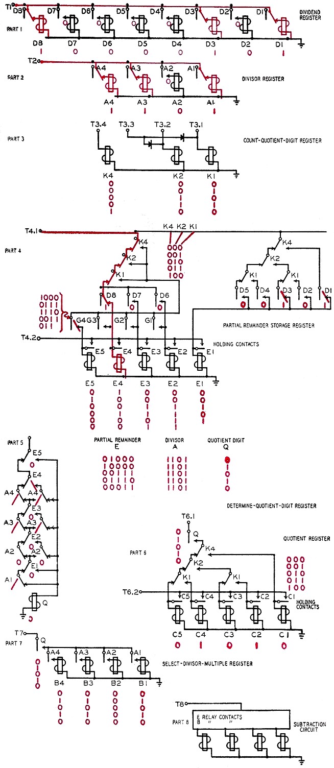
The circuit is on the opposite page. In part 1, terminal T1 is energized at the
start, and holds up the relays storing the dividend through their hold contacts.
(All current-carrying circuits and relay contacts in the energized state are in
red.) The actual number which these relays store, of course, depends on something
that happened before the time at which we begin. In the same way, the divisor is
stored in relays of part 2 of the circuit, and terminal T2 holds them up.
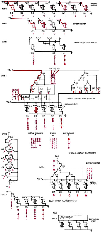
The circuit for doing long division with relays. Binary numbers
are for the process, and the circuits that carry current are shown in red.
Table I - Decimal to Binary Conversion
Now different things have to happen at different stages during the division.
So we want to have some relays that will tell us at what stage we are during the
process of the division. This is the function of the K relays of part 3 of the circuit.
The stages that they detect and report are 0, 1, 2, 3, 4. The time chart in Fig.
1 shows that stage 0 lasts from time 1 to time 8, stage 1 from times 9 to 16, stage
2 from times 17 to 24, etc. At stage 0, we attend to the first quotient digit; at
stage 1, we attend to the second quotient digit; etc. The red parts of the circuit
apply to the first stage of the division only.
We have to start off the divisions by selecting some digits, which we can call
a partial remainder (see part 4). At stage 0, this is the first four digits of the
dividend; but at later stages this is the result of a subtraction together with
"bringing down" one more digit of the dividend. The circuit of part 4 shows that
at each stage of the division, we have just the partial remainder that we desire
stored in the E relays. We have to look ahead to part 8, of course, and take on
faith that the G relay contacts in part 4 will express the result of a subtraction
that we want.
The next thing that we must do is decide whether the divisor "goes" into the
partial remainder, or whether it "doesn't go". To make this decision, we must compare
two numbers and decide which is the larger. The divisor "goes" and yields 1 as a
digit of the quotient if, and only if, the partial remainder is larger. A circuit
that does exactly this is shown in part 5. The red contacts show the original partial
remainder (stored in the E relays) and the divisor (A relays). We see that there
is no path for the quotient relay Q to be energized, and so the first "quotient
digit" is 0.
Before we go any further, we want to store that quotient digit, so that we shall
know the whole quotient when we get through with the division. This duty is performed
by the circuit of part 6, which shows how the digit quotient is routed, according
to the time it is obtained, into the right C relay.
We now want to determine the multiple of the divisor that depends on the quotient
digit and the divisor. This is the function of part 7 of the circuit, which will
give us the divisor itself if the quotient digit is one and zero in all digits if
the quotient digit is zero.
In part 8 of the dividing circuit, the subtraction of the divisor multiple from
the partial remainder is indicated schematically, because actual circuits for subtraction
were discussed previously.
The timing of the circuits, up to the end of the first two quotient digits, is
shown in the timing chart of Fig. 1. The same conventions are used here as in the
time chart for multiplication in the previous article. Successive time intervals
1,2,3,4, are shown from left to right. In the first column, the different terminals
are shown from top to bottom; in the second column, the names of the relays which
the terminals energize; in the third column the names of the relay contacts through
which the relays are energized. Each horizontal line begins when its terminal is
energized, and stops when its terminal ceases to be energized. There are some vertical
lines showing X's and O's. X marks the relays energized at a certain time, and the
O's mark the contacts through which they are energized.
Now, you may say, it is all very well to be able to add, subtract, multiply and
divide in binary notation, but how do we go from decimals to binaries?
In fact, even before we ask this question, we have to ask: how will the machine
take in a decimal number? In other words, how will the machine accept it, record
it, and store it?
Ordinarily a calculating machine (or some auxiliary part of it) will have a keyboard,
containing keys numbered 0, 1, 2 up to 9. Often the keyboard will have a different
column for each column of the number to be inserted in the machine. To put in a
number like 593, we press down the 5 key in one column, the 9 key in the next column,
and the 3 key in the third column.
In many calculating machines, the result of pressing down a key, say 3, is to
turn some little counter wheel 3/10 of one complete turn. But in our machine we
want the result of pressing down the 3 key to be the energizing of certain relays,
so that we can use the information later in the machine.

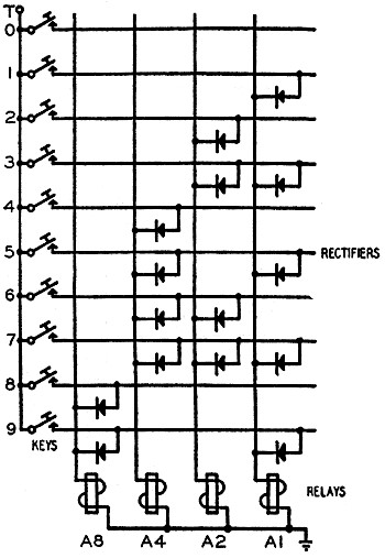
Fig. 2 - Circuit for converting a decimal digit to a 4-digit
binary number.
We would reasonably desire to convert anyone of these ten decimal digits o to
9 into a pure binary number according to Table I.
Fig 2 is a circuit which will do this (using 15 rectifiers and 4 relays).
For example, if we press the 3 key, relays A2 and A1 are energized, but not relays
A8 and A4, and so the information produced in the relay register is 0011, which
is the binary number three.
In this way the decimal number 593 can be converted into 0101 1001 0011 stored
in 12 relays. This form of representing a decimal number by a "code" for each digit
is coded decimal rotation.
Now how do we go from 0101 1001 0011 to what this number is in pure binary notation?
593 of course is 5 times 10 times 10, plus 9 times 10, plus 3, and all we have to
do is writs this in binary and tell our machine do it:
0101 times 1010 times 1010 plus 1001 times 1010, plus 0011.
And this our machine can do because it has an addition circuit and a multiplication
circuit. It will be neater to program this operation with:
5 times 10, plus 9,
all times 10, plus 3.
Thus for a ten-digit decimal number, we shall only need nine multiplications.
Binary to decimal
Now suppose that we have the opposite problem. Given a binary number, we want
to find the corresponding decimal number. We divide this number by 1010 (one-oh-one-oh,
or 8 plus 2, or 10 in binary) and find the remainder, which will be less than 10,
and store it. Then we take the quotient, and divide that by 1010, and store the
new remainder. And so on.
For example, suppose we desire to convert the binary number 10000101 into a decimal
number.
 which is 3 in decimal,
and becomes our first decimal digit. which is 3 in decimal,
and becomes our first decimal digit.
 which is 3 in decimal,
and becomes our second decimal digit. which is 3 in decimal,
and becomes our second decimal digit.

Fig. 3 - Circuit for converting 4·digit binary system digits
to decimal digits.
Our relay electric brain has division circuits and registers where we can store
remainders; and so we can convert from binary into decimal. In this case we obtain
the coded decimal form 0001 0011 0011 which is the same as 133.
How do we get this out of the machine? For example, suppose we have ten typewriter
keys, bearing the characters 0, 1, 2, 3, 4, 5, 6, 7, 8, 9. We wish to impulse these
keys in order. The circuit in Fig. 3 will do this. When terminal T is energized,
the appropriate K relay is energized, depending on the state of the A relays which
hold the corresponding binary number.
* Author: Giant Brains
(continued next month)
Posted April 20, 2021
|