|
March 1954 Radio-Electronics
 [Table of Contents] [Table of Contents]
Wax nostalgic about and learn from the history of early electronics.
See articles from Radio-Electronics,
published 1930-1988. All copyrights hereby acknowledged.
|
The G-Line (aka
G-String) RF transmission system is a rather amazing invention contrived
through out-of-the-box thinking by its inventor, Dr. George Goubau (from whence
the "G" in the name derives). He determined that a sort of waveguide could be
made with a single conductor surrounded by insulation with a specific dielectric
constant that would cause the dielectric-air interface to reflect the wave in a
manner similar to atmospheric channels that facilitate long distance
communications. The G-Line is designed to efficiently transmit UHF television
signals (470 - 806 MHz), and like a waveguide exhibits a lower cutoff frequency
(~300 MHz), thus acting like a highpass filter. G-Line has its weak points, like
that it must not come near to obstacles that will affect the dielectric-air
interface or the line will radiate like an antenna. Also, over time the
insulation cracks and/or absorbs moisture and changes the impedance parameters,
thus affecting the transmission characteristics. History has shown that the
G-Line never became a practical means for widespread commercial use even though
the article states it would be good for hostile environments.
G-Line
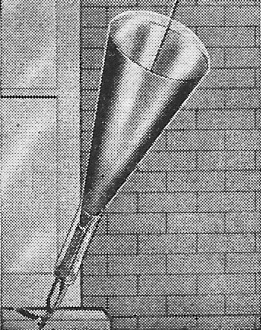
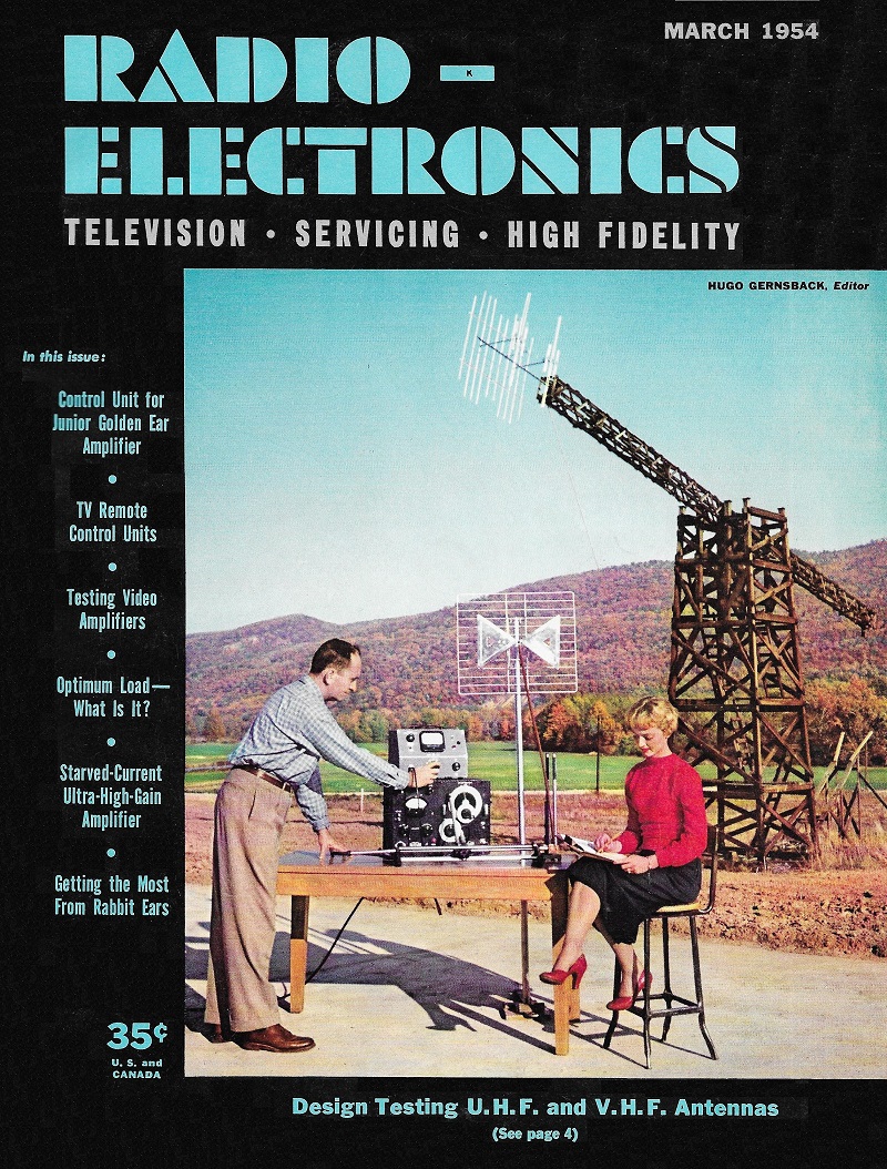
The launcher (from the antenna) and the catcher (at the window) match the G-line
to the 300-ohm lead. Photos courtesy of David Bogen Co., Inc.
 One of those fantastic scientific conceptions that seem fitted only for expression
in long strings of mathematical calculations has come down to (or near) Earth, and
may soon be seen on rooftops carrying u.h.f. TV antennas.
The new science-fiction-like apparatus is the G-line being made and sold as u.h.f.
lead-in by Bogen. To all appearances, it is a single wire ending in a horn-like
device at each end. (See photos and Fig. 1.) But radiomen know that u.h.f. does
not travel readily on a single piece of wire. It tends to radiate off the wire into
space, so little gets to a point any distance along the wire. For u.h.f., very special
twin-line, coaxial or other types of transmission lines are needed, and even their
losses go up rapidly with frequency. Is this new line some special kind of wire?
The G-line, so called after its inventor, Dr. George Goubau (Radio-Electronics,
May, 1950, and June, 1951) is a very special piece of wire. The ultra-high-frequency
currents travel, not in the wire itself, but in the insulation around it! (To be
more exact, they are confined to the area around the wire by the difference between
the dielectric value of the insulation and that of the air around it.)
This is not as hard to understand as it may seem. We are all familiar with coaxial
cable. At higher frequencies, the center conductor of the cable may be removed;
and we have a waveguide. We know that u.h.f. current can be piped down waveguides
without trouble. The G-line; in effect, removes the outer conductor, using only
the inner one. The only difficulty is that we might expect the u.h.f. to radiate
out in all directions from the wire, and that little would reach the end. This is
just what does happen on an ordinary piece of wire.
As the waves spread outward from the wire of the G-line, they are reflected back
toward it again by the boundary between the insulation and air. The short waves
(3-30 mc) are similarly confined to the area near the surface of the Earth by bending
due to the thinning out of the atmosphere. Waves which are not too near vertical
are reflected back toward the Earth, instead of going on into space.
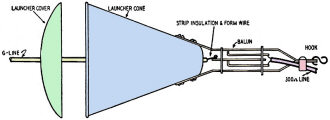
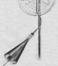
Fig. 1 - Diagram of launcher and balun with lead-in and G-line connections.
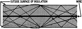
Fig. 2 - Exaggerated illustration showing r.f. traveling between wire and surface
of the insulation on G-line.
Thus, in the G-line, signals travel much as in the exaggerated drawing of Fig.
2. The signals are picked up by an ordinary antenna with a balanced impedance of
about 300 ohms. Therefore they must be launched onto the single (unbalanced) line.
The launcher includes - at the narrow end, a balun (balance-unbalance transformer)
and a gradually widening horn. The signals which may at first be inclined to treat
the wire-horn combination as a new kind of coaxial finds the impedance rapidly going
up as the horn widens, so that more and more of it follows the center conductor.
A similar unit at the end where the lead enters the house transforms the signal
back to a, balanced one and puts it on a standard 2-conductor 300-ohm line. The
two matching units contribute a loss of only 1/2 db each, and the line itself has
a loss of 1 db per hundred feet. Radiation and noise pickup are very low because
of the self-contained nature of the line, and it has an almost complete cutoff below
300 mc.
Insulation presents a problem. While the field falls off rapidly with distance
from the surface of the wire, anything approaching it closely would cause severe
losses. Therefore the line is supported wherever necessary by loops of nylon cord
stretched between the ends of a small bracket, so that a minimum of solid material
is brought near the line. Similar brackets are used wherever a bend is made, as
the line must not have sharp turns, and 3 supports are needed for a 90-degree bend.
The new line will be especially useful wherever long runs have to be made. It
will also be valuable in bad-weather and industrial areas and salt-air installations,
since moisture, soot, or salt do not increase its losses.
Posted May 18, 2022
|