|
August 1949 Radio-Electronics
 [Table of Contents] [Table of Contents]
Wax nostalgic about and learn from the history of early electronics.
See articles from Radio-Electronics,
published 1930-1988. All copyrights hereby acknowledged.
|
A well-planned and
installed waveguide system is always impressive. With enough switches, couplers,
transitions, adapters, and various and sundry other accoutrements, the result
can be downright artistic in appearance. Although usually the most costly form
of electromagnetic wave transmission, it has the decided advantage of having by
far the lowest path loss and highest isolation of any of the other forms of
transmission - over the air, coaxial cable, twin lead, etc. This, Part IV of an
VIII-part series on microwaves by author C.W. Palmer, appeared in the August
1949 issue of Radio-Electronics magazine. He discusses E- and H-planes,
inductive and capacitive "windows," tuning screws, proper joining of waveguide
sections, and more.
Microwave Series -- Part 1: How Radio Waves
Can Be Transmitted Inside Pieces of Pipe (4/49), Part II: An Introduction to Standing
Waves, Cavity Resonators, and Representative Examples of u.h.f. Plumbing (5/49),
Part III: Tubes for the Microwave Frequencies, Giving Special Notice to the Lighthouse
Triode, Velocity-Modulated Tubes, and the Magnetron (6/49),
Part IV: How
Waveguides Are Joined and Tuned for Lowest Possible Loss (8/49),
Part V: Special
Sections of Waveguide Are Employed as Transformers (9/49),
Part VI: Some Equipment
Used for Measuring Frequency, and Crystals for Receiver Frequency Conversion (10/49),
Part VII: Action of Below-Cutoff Attenuators and of TR and Anti-TR Switches
(11/49),
Part
VIII: Receiving and transmitting antennas for microwave communication.
How Waveguides Are Joined and Tuned for Lowest Possible Loss
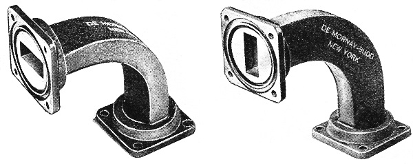
Fig. 1 - In bending waveguides, use is made of either the E or
the H bend. Both appear here.
Part IV - How waveguides are joined and tuned for lowest possible loss
By C. W. Palmer
DeMornay Budd Photo
So far we have learned how waveguides are used to transfer microwave radio power
from an oscillator or transmitter to an antenna, and from the antenna to the receiver's
amplifying and detecting circuits.
We have learned that the familiar radio quantities - inductance, capacitance,
impedance, reactance, and resistance-are found in r.f. plumbing, but that their
appearance is entirely new. And since we are dealing with wave propagation instead
of conduction of r.f. currents as in low-frequency radio, we must learn a new set
of rules.
In this part of the microwave series we will attempt to express those rules in
a form that will help the radio man to understand better the do's and don'ts of
r.f. plumbing.
One of the most important things to learn in using waveguides is to avoid discontinuities
or changes in the internal mechanical shape of the guide from one section or piece
of apparatus to an-other when joining them together in a "circuit."
Look at Fig. 1 as an example. It shows two types of L bends used extensively
in r.f. plumbing. The first is known as an E bend, and the second is called an H
bend. It is easy to remember which is the E and which the H bend if you think of
the E as the "easy" and the H as the "hard" bend (if it were possible just to bend
a piece of straight guide to make a right-angle turn, which it isn't).
In manufacturing these bends, deviation from the inside dimensions of the straight
section by even a few thousandths of an inch in the bent portion will increase the
loss from a nominal 0.02 decibel for such a section to several decibels, with a
corresponding increase in the standing-wave ratio.
Fortunately such discontinuities can be taken care of by introducing into the
guide obstacles that produce reflections which cancel the unwanted ones.
The matching devices most commonly used are diaphragms and tuning screws. The
diaphragm, or window as it is sometimes called, is an aperture of thin metal placed
across the waveguide. Such a window introduces either inductive or capacitive reactance
depending on the direction of the slit.
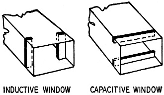
Fig. 2 - The inductive and capacitive windows.
Fig. 2 shows inductive and capacitive windows. For an inductive window the edges
of the slit are parallel to, and for the capacitive window perpendicular to, the
electric field. Usually these windows are soldered in place and are not variable.
Where large amounts of power are to be carried in the waveguides, inductive windows
are preferred because the capacitance type breaks down, causing arcing and loss
of power.
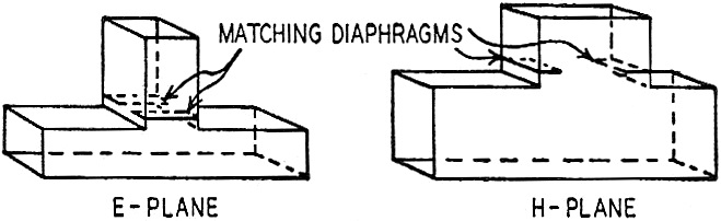
Several examples of the use of fixed windows in waveguide circuits are shown
in Fig. 3, which shows E and H tees used for branching or splitting the waves into
two paths. The windows in these tees balance out reflections that would otherwise
be introduced by the branch line and would introduce losses in the main waveguide
path.
Sometimes it is desirable to have a variable reactance in a waveguide set-up
to permit balancing out undesired reflections. In such cases tuning screws - small
cylindrical posts projecting into the broad face of the guide as shown in Fig. 4
- are used. These screws provide capacitive reactance which varies with the penetration
of the post into the guide. A single screw may be sufficient, but usually three
screws are provided at quarter-wave-length intervals along the guide.
Sometimes it is desired to insert in a waveguide a device that will either pass
a desired mode (modes of propagation were discussed in Part I) and no other, or
reflect completely the power in a certain mode. Resonant diaphragms or windows are
used for this purpose. A thin rectangular ring of the proper dimensions placed across
the inside of the rectangular waveguide and separated from it by insulation will
reflect, for example, all the T E0,1 mode transmitted through the guide.
If a thin metal diaphragm across the guide is provided with an opening of the
proper size, all the power in the T E0,1 mode will be transmitted.
Resonant slits in the waveguide diaphragms are also useful for passing waves
of low power and rejecting those of higher power. The slit is so narrow that breakdowns
occur, and the resonant condition is temporarily removed. A device of this sort
is useful for preventing the direct power of a transmitter from reaching and damaging
a receiver connected to the same antenna system, during transmit periods, while
allowing incoming radio waves to be received normally. In a radar system a special
form of such a device is called a TR or ATR box, and will be discussed in detail
later.
A microwave primer
It is frequently necessary to use long stretches of waveguides, and it is very
unusual for them to proceed in a straight line. Bent and twisted sections with the
bends in both E and H planes, tees for branch lines, etc., must be used to fit the
needs of the individual installation.
In using these lengths with tee's, L's, etc., certain rules must be observed
to obtain the desired results. These are summarized here in the following eight
items.
1. A shorted end of waveguide (as the side arm of a tee or a stub) an odd number
of quarter wavelengths long reflects an "opening" where it joins another waveguide.
Waves in the main arm would travel into such a side arm as well as traveling through
the main arm.
2. A shorted end of waveguide any number of half wavelengths long reflects a
"solid wall" where it joins another waveguide. Waves in the main arm of a tee would
travel through without entering such a side arm for this reason.

Fig. 3 - Windows used in waveguide branch.
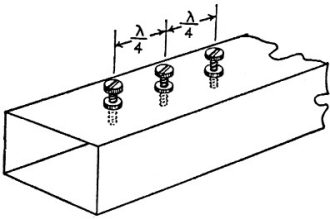
Fig. 4 - Tuning screws for varying reactance.
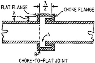
Fig. 5 - The choke flange, perfect connector.
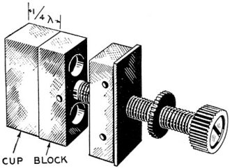
Fig. 6 - The cup-type plunger reduces losses.
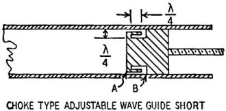
Fig. 7 - Improved plunger uses choke circuit.
3. A quarter-wave section of wave-guide has opposite impedances at its ends (if
impedance is high at one end, it is low at the other) just as in ordinary types
of co-axial and parallel transmission line. (This summarizes rules 1 and 2.)
4. The Q of a waveguide is a function of frequency and also depends on the ratio
of volume to inside area of the guide. Q's of 25,000 are not uncommon in waveguides
and resonant cavities.
5. The characteristic impedance differs with different modes of operation. In
a rectangular waveguide the impedance is proportional to the narrow or b dimension
of the guide. It varies from about 475 ohms to zero as the b dimension is reduced.
6. The wavelength in a hollow wave-guide (as measured in a slotted waveguide
section) is always greater than the wavelength of the same wave in air, due to the
multiple reflections from the walls of the guide.
7. Sections of open and closed waveguides may be used as switching circuits by
applying the principles of Rules 1 and 2 above.
8. Standing waves in waveguides are checked in a manner similar to that used
for co-axial lines. A section of waveguide with a narrow slot parallel to the axis
of the guide is used. A probe with a crystal detector or a small fuse (1/200 ampere)
heated to almost the blowing point by direct current is used to detect the presence
of standing waves as with a slotted co-axial line at lower frequencies.
Joints in waveguides
Sections of waveguide may be soldered together end to end. If the sections line
up and touch, losses and reflections introduced by the joints are negligible.
However, for maintenance purposes and to make waveguide apparatus useable in
more than one installation, it has become common usage to terminate waveguides with
flanges on the ends which are soldered to the guide and machined flat on the ends.
These flanges are bolted together. Experience has shown that this type of joint
can be made better than even the average soldered guide-to-guide joint if care is
taken to make uniform contact.
To reduce further the possibility of losses due to waveguide joints, it is considered
good practice to use the "choke flange" joint, butting a choke flange always against
a flat one.
The principle on which this choke flange works can be readily understood from
waveguide Rule No.2 above. See Fig. 5. This shows a cross-section view of a choke-to-flat
joint. The slot left by the junction of the two waveguide sections is a half wavelength
long at the optimum frequency of operation of the waveguide, which means that the
side cavity A reflects a "solid wall" to the main guide so that there can be neither
leakage of r.f. nor dicontinuity to cause reflections in the main guide path.
In addition to the above, the point B where contact is actually made between
the two waveguide sections is at a point of zero current, and perfect electrical
contact need not be made between the two sections as is necessary in joining two
flat flanges.
Such choke couplings are frequently used as "wobbly" or nonrigid connections
between waveguide sections. They are used, for example, at the junction of an antenna
where it is desired to shift or rotate the final section of guide to orient the
antenna for peak response.
As a rigid connection the loss in a choke-flange joint is in the order of 0.02
db, compared to about 0.05 db for a well-made contact joint. The nonrigid connection
mentioned, with a gap of about 1/16 wavelength between the choke and flat flange,
has a leakage of about 0.3 db.
Plungers for shorting bars
In terminating side arms as described in the rules above, it is sometimes desirable
to make movable shorting plates or plungers so that the lines can be tuned exactly
to a desired quarter- or half-wavelength point.
Plungers can be either solid blocks, cup terminations, or choke terminations.
The solid blocks must make good electrical contact at all points around the edge
with the inside of the guide, or behavior will be erratic as the plunger is moved
and power may leak past the termination.
Better results are obtained with a cup contact as shown in Fig. 6. Contact is
made with the inside walls of the guide a quarter wavelength from the plunger, where
the flow of current in the walls of the guide is zero. Losses in this type of termination
can be held to as little 0.08 db.
An improved termination is the choke plunger which uses the same principle as
the choke coupling. As shown in Fig. 7, no mechanical contact with the inside walls
of the waveguide is made at the front surface of the plunger. Contact is made at
B where the current is zero. Choke plungers have losses in the neighborhood of 0.02
db.
Dielectric in waveguides
The fact that the introduction of a dielectric inside waveguide will decrease
the "cutoff" wavelength has been used practically in a so-called "line stretcher."
This device introduces controlled amounts of dielectric into the guide to tune it.
The effect of an ideal dielectric in a waveguide is to increase its apparent
size. It also lowers the impedance in all but one TM (transverse magnetic) mode.
The losses of a guide filled with solid or liquid dielectric are higher than for
an air-filled or gas-filled guide. However, the effect is slight.
An exception to the above and a point of caution to the experimenter in microwaves
is the effect of water. Small amounts of water condensed on the inside of a waveguide
may introduce losses up to 1/2 decibel per foot of waveguide. This is caused, not
only by the large dielectric loss characteristic of water at high frequencies, but
also by the high dielectric constant of water. This is why some waveguide installations
are pressurized or, charged with an inert gas.
Posted October 4, 2021
|