|
November 1953 Radio-Electronics
 [Table of Contents] [Table of Contents]
Wax nostalgic about and learn from the history of early electronics.
See articles from Radio-Electronics,
published 1930-1988. All copyrights hereby acknowledged.
|
Unless you are into
restoring and/or repairing radios with dial cords, you probably can't fully
appreciate the humor in this short piece from a 1953 issue of
Radio-Electronics magazine. Dial cord is a type of string that does not
stretch when put under tension. It is wound around the shafts of two or more
components to keep them in step with each other. Since the advent of LED and LCD
readouts for displaying the tuned frequency, there was no need to mechanically
synchronize a sliding or rotating pointer with the position of a (usually)
multi-plate tuning
capacitor. If you are/were lucky, the path of the dial cord simply wrapped
around the shaft of the tuning element (capacitor) and around the axle of a
circular tuning dial, with no pulleys or bobbins for changing the direction.
Such is the case with my
Crosley
03CB console radio. Nightmare scenarios, as jokingly referred to in this
story, are like that of the dial cord in my
Realistic Patrolman-50 AM/FM/Shortwave radio where the path was a
torturous set of windings clockwise two times around one wheel then around the
direction-changing pulley and three winds in a counter-clockwise direction on
the next wheel, etc., etc., etc. That was while keeping the cord at just the
right tension to assure smooth operation without any slipping or binding.
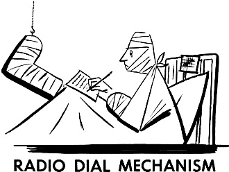
Radio Dial Mechanism
 National Service Manager National Service Manager
Superoptic Radio and TV Corp.
Ninety Six, S. C.
Dear Sirs:
Thank you very kindly for the instruction sheet which you enclosed with the new
dial cord and pointer kit for replacement in your model T-175. There is some question,
however, as to the completeness of the installation procedure as outlined on the
sheet. The following are a few points that might be added:
First, as the cord is grasped firmly in the left hand and the dial spring is
held in the right hand (as shown in the instructions), I found no trouble in threading
the cord around drum A, through eyelet 3A and under slider X. However, I think it
should be noted that in order to cut the cord at W while spring R-1 is stretched
to 1.1 inches and the dial pointer is located at 720, it is necessary to transfer
the cord (W-1) so that it is held between the teeth, so the left hand is free to
cut the cord at H.
Also, since the dial drum tends to move while stretching spring R-1, it is necessary
to remove one shoe (preferably the right) and place the big toe through cutout S-1,
under plate 7 of variable capacitor C17A, being careful not to bend the plates with
the toenail. A note of caution is also necessary in the instructions for stretching
tension spring B-7 to point A; since in case the spring is pulled beyond point A,
serious injury may result to the right elbow (required to hold drum C from falling
off shaft T while set-screw S-19 is loose). In addition it should be advised that
a first-aid kit be kept handy while looping cord 2 through hole F and around drum
G. It seems that this procedure often causes heavy pressure on springs L-1 through
L-7, resulting in their flying in all directions around the room.
My second suggestion is to provide a procedure for setting the dial pointer P1
to indicate 720 on the dial. Since it is required to set the pointer before cutting
the dial cord, and since the cord cannot be cut until spring R-1 is stretched to
exactly 1.1 inches, some difficulty may be encountered. Remember that the left hand
is holding cutting pliers; the right hand is stretching spring R-1; the teeth are
holding cord Y; the left knee is preventing the chassis from falling off the table;
the right elbow is holding drum C on shift T; and the right toe is inserted in cutout
S-1 under plate 7 of variable capacitor C17A. It is therefore necessary that a board
(not supplied with kit) be propped up behind the dial plate between J and D to apply
pressure to the slider at Z. This will hold the dial pointer exactly at 720. Extreme
care must be taken in placing the board on the slider since the board will tear
the speaker cone completely off the speaker frame if it slips.
After cutting the dial cord (at point was shown on the instructions) it was found
that a note of final warning should be included on the instruction sheet. The heavy
tension caused by spring R-1, when stretched to 1.1 inches, results in the sudden
revolving of dial drum C (despite the pressure of the elbow against it). Dial drum
C will then spin off of shaft T and spin across the front of the chassis, breaking
tubes V1, V2, and V3, unless they have been removed.
Also, please note my order for another installation kit of the same type - the
original was ruined when the cutter slipped. Please send the kit as soon as possible,
since my physician advises me that I will be on my feet again in a few weeks.
Very truly yours,
Herbert Michels
Posted October 12, 2020
|