Printed Circuits for Home Use |
||
When you think of printed circuits, probably what comes to mind is what is really a photo-etched circuit board. In the early days of printed circuits a lot of the circuits actually were "printed" on a substrate of some sort. A silkscreen process was often used for low resistance interconnects and printed inductors, as well as for printed resistors on materials like fiber, plastic, phenolic, and even (yikes) asbestos board. There is still what is called a thick film screen printing process used today primarily in military systems, but overwhelmingly the photo etching process is used to generate circuit boards. In the era of vacuum tubes, it was not uncommon to have grid biasing circuits printed directly on the glass enclosure using a resistive paint and then trimming for the target resistance by removing excess material. This 1950 Radio & Television News magazine article shows an example of a circuit printed on a 6J6 twin-triode tube. Printed Circuits - Part 2
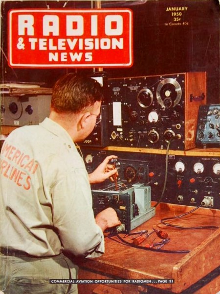
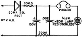
Fig. 1 - Kit of printed circuit paints made by Microcircuits Co. of New Buffalo, Michigan. The code oscillator (see circuit. Fig. 6) is built from kit. By John T. Frye A discussion of the techniques and equipment used in making printed circuits for home-built units. Part 1 of this article, appearing in the December 1949 issue, presented the various methods by which these miniature circuits are produced commercially. Now we are ready to roll up our sleeves and get down to the pleasurable business of making our own printed circuits. A quick review of all the methods of producing these circuits reveals that the simple brushing of conductor and resistor paints onto a base plate is the most practical way to start experimenting. Such a system requires an absolute minimum of equipment; yet it produces results that compare quite favorably with the much more complicated methods used in mass production. The first things we need are conductor and resistor paints. There are two kinds of conductor paint in general use - copper and silver. The copper paint is cheaper, but its resistance increases with age to a terminal two to five ohms per inch. Silver paint, on the other hand, will maintain its resistance of only a few tenths of an ohm per inch for years. In all circuits except temporary experimental ones, the silver paint is well worth its additional cost. Next, we need two or three different mixtures of resistor paint. More than one degree of conductivity is needed if we are to be able to draw a wide range of resistance values and still keep our resistors of reasonably uniform size.
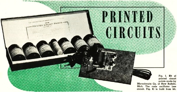
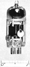
Fig. 2 - Two-stage amplifier painted on the glass envelope of a twin-triode 6J6 tube. We shall also need a solvent material that can be used to thin the paints when they become too thick through evaporation, and to clean the brushes. In addition, we should have a good insulating lacquer, the uses of which will be described later. Finally, we must provide ourselves with base materials upon which we can draw the printed circuits. We could prepare our own paints, but most of us do not have the materials, facilities, nor inclination to do this. Fortunately, it is not necessary as the paints can be purchased already prepared. The E. I. duPont de Nemours Co., Inc., the Metaplast Co., Inc., and the Acheson Colloids Corporation are among the companies that supply these paints commercially, but it is doubtful if they would be interested in supplying small quantities. The Microcircuits Company of New Buffalo, Michigan, however will supply any quantity of needed materials. In fact, they sell a "kit" of supplies for the beginning experimenter that is illustrated in Fig. 1. This kit includes a bottle of copper paint, another of silver paint, three resistor paints of different degrees of conductivity, a bottle of lacquer, and a bottle of thinner and brush-cleaner. Just about any material, if it is properly prepared, can be used as a base upon which to paint the circuits. The only requirements are that the material be rigid so that it will not flex and cause the lines painted upon it to crack; that its surface be not too rough or porous; that it be chemically inert; and that it have an insulated surface or one capable of being insulated. The paints do not stick too well to glass unless the surface has been roughened by sand-blasting or etching; but the experimenter can overcome this by applying a thin coat of lacquer to the glass and then painting his circuits on this coating. Fig. 2 shows a complete two-stage amplifier circuit painted on the envelope of a 6J6 tube. Asbestos board, fiber-board, etc., can be used; but if the surface of this porous material is not treated, absorption will cause the characteristic values of resistors painted upon it to be greatly changed. A sealing coat of lacquer will avoid this trouble. The paint adheres very well to plastics because the solvent used causes the surface of many of them to become slightly dissolved. A heat-resisting coating on a metal base works quite well, for the metal aids in carrying the heat away from the resistors. Two coats of lacquer will provide such a coating.
Fig. 3 - (Top row) Four-tube receiver printed on 3/32" Lucite plate. 2" wide and 5" long. At left is stenciled silver wiring with complete receiver at right. (Center) Four-tube receiver printed on thin steatite plate. (Bottom row) Development of a four-tube receiver on thin steatite plate 2" wide and 3" long. The plate at left had paints applied with a brush except for spiral inductances. The center one was stenciled. Leads from the complete receiver at right connect to batteries and speaker. All receivers use square law detector, two stages of pentode amplification, and triode output.
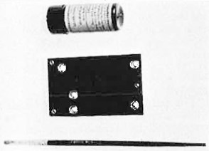
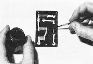
Fig. 4 - A base plate all ready for the painting of conductors. Note that brass rivets are used as terminals and to form crossovers.
Fig. 5 - Actual painting of resistors. Note how resistance lines are lapped over the conductor lines and preparation of abutments.
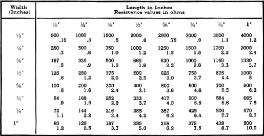
Table 1 - Resistance and wattage values for various sizes of resistors painted with one kind of resistor paint. The intersection of the width and length values gives the resistance value above and the wattage rating below. For example, a resistor 1/4" wide and 3/4" long has a resistance of 1500 ohms and a wall age rating of 1.8.
Table 2 - Characteristics of some typical subminiature tubes used in printed circuits.
Fig. 6 - Circuit diagram of the code oscillator shown in the photograph of Fig. 1.
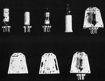
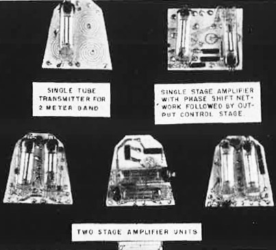
Fig. 7 - Five types of grid-modulated 132-144 mc. transmitters. The two at the top left are painted on thin steatite cylinders housing subminiature tubes. The one top center is printed on the envelope of the 6K4 triode. The second from top right is painted on the envelope of a T-2 subminiature type tube while the circuit at top right is a flat-plate transmitter. The bottom row (left) shows front and back views of a plate transmitter with the completely assembled transmitter at the right.
A self-explanatory photograph of various printed circuit units. No matter what base is used, the cardinal principle is that the surface receiving the paints must be absolutely clean. The slightest trace of grease, even that left by the touch of a finger, will prevent the paint from making a good bond with the base. Lacquered surfaces must not be touched. Glass, porcelain, and plastics can first be cleaned with alcohol, gasoline, or carbon tetrachloride, then washed with soapy water, and finally thoroughly rinsed with clear water and dried. Laying out the circuit should be done with great care. Conducting lines should be as short and direct as possible. "Cross-overs" of conducting lines should be held to a minimum. Correct spaces should be left for resistors. Terminals should be provided in the form of rivets. The possibility of inductive and capacitive effects between adjacent conducting lines must be considered. All of these details should be worked out with paper and pencil, and then the complete diagram can be transferred to the base plate by means of carbon paper. When actually drawing on the base with a pencil or drawing ink, it must be remembered that these lines are conductors in themselves and must not be left where they will connect parts of the finished circuit. Fig. 4 shows a base plate of laminated paper and phenolic material all ready for painting. Brass eyelets have been inserted at the proper places to furnish terminals; the small brush and the silver conducting paint are all ready to paint the conducting lines. Before starting to brush on the paint, though, it is important to see that the paint is very thoroughly mixed. Remember our "paint" is composed of metal particles and a carrying solution. When undisturbed, the heavy particles settle to the bottom and stay there. A line drawn with a brush dipped into a bottle of this undisturbed paint would consist chiefly of non-conducting thinner and be a very poor conductor. Lengthy stirring will mix the paint, but that makes it necessary to have the bottle uncorked while doing the stirring. The thinner used is extremely volatile so that the drying time will be short, and if the bottle is left un-stoppered for any appreciable length of time, the paint becomes too thick to brush. A temporary cover should always be set on top of the bottle of paint except when the brush is inserted. A quick stirring followed by lengthy shaking of the stoppered bottle is the best way to mix the paint, and it should be kept mixed by repeated shakings during the painting process. The conducting lines should be carefully drawn along the direction of current flow, care being taken to make the lines of as nearly uniform thickness and width as possible. The paint should be run up over the edges of the eyelets to make sure that a good electrical connection is obtained at these points. "Abutments," across which the resistors will be bridged should be drawn in as shown in Fig. 5. The manufacturer of the paint used will provide information on the drying time required. In the case of the Microcircuits silver paint, the air-drying time is one half hour to an hour. Copper and resistance paints take considerably longer. The process can be speeded up by mild heating, not over 1500 F., in an oven or with an infrared lamp. Greater heat than this may result in "bubbling" of the paint. When the silver paint is dry, you are ready to paint in the resistances. Painted resistors are figured from a standard resistor one inch square, painted with a single thickness of the given paint, and having a heat dissipation of ten watts. As you know, the resistance of such a resistor will be directly proportional to the length measured along the direction of current flow and inversely proportional to the width and the thickness. The wattage rating varies directly with the surface area. Reductions in the dimensions of this standard square will result in other resistors whose resistance and wattage values are in accord with these laws. The resistance may be higher or lower than that of the standard resistor, depending upon whether the "width" or the "length" of the square was reduced. Table 1 shows the different values of resistance and wattage obtained when a standard resistor of 500 ohms is reduced in 1/8" steps along its width or length or both. In the same way, when you know the resistance of a standard one-inch-square resistor painted with a particular resistance paint, you can always estimate the dimensions of a needed resistor whose value lies within the range of that particular paint. The resistors should be drawn with a thick, even layer of paint that overlaps the silver paint by at least 1/16" If the resistor is of uneven thickness, the heat generated by the 12R losses will be unequally distributed and may cause the resistor to be damaged when operated near its maximum wattage rating. After the resistors have dried for fifteen minutes, they may be baked at up to 250° F. without danger of bubbling. The cold resistance of a resistor that has been baked at 200° F. is about one half that of the same resistor with normal air-drying; so the method of drying should be taken into account when calculating the size of resistors. It is impossible to avoid having some crossovers of conducting lines, and there are two ways of making them: first, you can bridge one of the lines with a piece of paper that has been soaked in an insulating varnish, shellac, or lacquer; and, after it has thoroughly dried, you can paint the other line right over the top of this bridge. The other method is to place a brass or copper rivet on each side of the line to be crossed and then carry the crossing line down through one of these rivets to the opposite side of the base plate, along a conducting line to the other rivet, and then back up. This latter scheme is more permanent and is less likely to cause trouble because of any high capacitance between the crossed conductors. As mentioned in Part 1, small condensers can be painted by using silver-painted areas on opposite sides of the base plate, especially when the plate is of thin, high-dielectric material; but the experimenter will find it much easier and more accurate to use the tiny disc-type ceramic condensers by connecting them to the conducting lines at the points needed. These condenser leads, as well as tube leads, transformer leads, etc., can be connected to the painted lines by either soldering or painting. When soldering, the painted surface is first sanded clean and a drop of solder placed on it and flattened out; then the tinned conductor is placed on this drop of solder, which is. re-melted just enough to bond it to the conducting lead. In order to get the "feel" of drawing printed circuits, it is a good idea to reproduce in miniature some simple electronic device such as the code oscillator shown in connection with the Microcircuits kit; but the real field for these printed circuits lies in those pieces of equipment where the reduction in bulk and weight is of actual and not just "curiosity" value. Careful study of the accompanying pictures of transmitters, receivers, and amplifiers will show the reader what has been accomplished along these lines by expert technicians and will provide him with many valuable pointers in regard to layout, printing of inductors, tube-placement, etc. While standard components can be used with printed circuits, there is not much sense in using a log-chain leash on a Pekingese or in employing a tube or transformer that is five or six times as big as all of the rest of the circuit. Subminiature tubes and the other tiny components used in hearing aids make ideal companion units for printed circuits, and practically all of them will be found advertised in the pages of RADIO & TELEVISION NEWS. Table 2 gives subminiature tube characteristics that will be found useful in designing printed circuits. In conclusion, the writer would like to say that he never could understand what pleasure the head-hunters got out of shrinking the noggins of their enemies to the size of a human fist; but he knows there is a very decided thrill in building equipment in about one-tenth the space normally required.
Bibliography Bradley, Robert F.; "Design and Repair of Printed Circuits." Brunetti, Cledo & Curtis, Roger W.; "Printed Circuit Techniques," National Bureau of Standards, Circular 468. Brunetti, Cledo & Khouri, A. S.; "Printed Electronic Circuits," Electronics April 1946. Pritikin, Nathan; Glass Products Co., Inc. Schwab, M.; "Printed Electronic Circuits," Centralab Div.
Posted June 23, 2022 |
||