|
Selenium rectifiers
were the first widely used as other-than-vacuum-tube circuit elements for various power
supply designs. They were not very practical as detectors in receiver circuits unless
signal levels were high. Properly manufactured selenium rectifiers were much more
rugged and reliable than the tube equivalents, but generally were more expensive.
Since the power supply is such a critical part of any electronic assembly, the
tradeoff could be justified if only for the boost in a product's reputation for
having fewer breakdown issues.
This 1956 article in Radio & Television News magazine focused on "cartridge type" components, as opposed to the more bulky stacked plate type
(see other articles listed below). While it is true that there are not many applications
anymore for selenium rectifiers, vintage materials and methods sometime experience
a reincarnation in some other form using modern formulations and manufacturing techniques.
Having knowledge of previous work can help spawn ideas for research and development
toward solving new problems.
Electronics magazines of the era published many articles about selenium
rectifiers, including
After Class: Working with Selenium Rectifiers,
The Semiconductor Diode,
New Selenium Rectifiers for Home Receivers,
Selenium Rectifiers,
Applications
of Small High-Voltage Selenium Rectifiers, and
Using
Selenium Rectifiers.
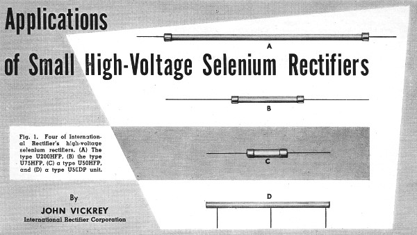
Applications of Small High-Voltage Selenium Rectifiers

Fig. 1 - Four of International Rectifier's high-voltage selenium
rectifiers. (A) The type U200HFP, (B) the type U75HFP, (C) a type U50HFP, and (D)
a type U50DP unit.
By John Vickrey
International Rectifier Corporation
Details on several popular and practical circuits which afford tubeless rectification
for special applications.
Cartridge-type selenium rectifiers have brought simplicity and compactness to
the design of high-voltage supplies. Tubeless operation results in freedom from
warm-up time filament circuit complications, reduced heat radiation, increased ruggedness,
unlimited life, and reduction of space requirements.
International Rectifier Corporation's high-voltage, cartridge-type selenium rectifiers
are obtainable with ratings up to 9.9 kilovolts r.m.s. input for single units. These
single rectifiers may be employed in conventional and special voltage doubler, tripler,
and quadrupler circuits, as well as in simple half-wave and full-wave circuits.
Polyphase operation is also possible, as with lower-voltage rectifiers. Besides
half-wave units, standard cartridges are available in full-wave center tap, voltage
doubler, and single-phase bridge types.
Typical applications of these rectifiers include insulation test equipment, capacitor
breakdown testers, magnetic amplifiers, bias supplies, oscilloscope high-voltage
d.c. supplies, television high-voltage supplies, radiation detecting instruments
(Geiger and scintillation counters), electrostatic dust and smoke precipitation,
electrostatic spray painting, photoflash high-voltage supplies, photomultiplier
tube supply, arc suppression in contact protection circuits, and many similar uses.
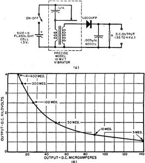
Fig. 2 - (A) Schematic diagram of a midget, low-current, high-voltage
supply which is completely portable and self-contained. It operates from a 1 1/2
volt flashlight cell. (B) A current versus voltage plot for various values of load
resistance, R.
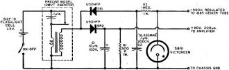
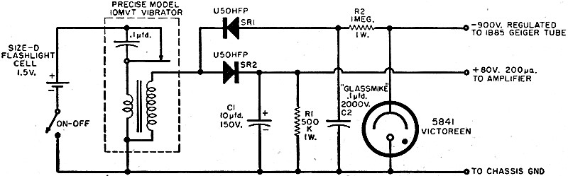
Fig. 3 - Vibrator-type power supply for a Geiger counter. It
furnishes 900 volts.
The accompanying illustrations show practical circuits for several small-sized
devices employing selenium rectifiers to obtain high d.c. voltages. The simplicity
of these devices, resulting from tubeless rectification, is evident. While each
circuit is intended for a specified application, other uses will suggest themselves.
Portable High-Voltage Supply
Fig. 2A shows the circuit of a midget, low-current, high-voltage supply. Operated
from a single Size-D 1 1/2-volt flashlight cell, this unit is completely portable
and self-contained.
The high a.c. voltage is supplied by a small vibrator transformer, Model 10MVT
(Precise Measurements Company, Brooklyn 23, New York). This component is completely
encapsulated and requires only four connections, two to the battery circuit and
two to the rectifier-output circuit. The interruption frequency is approximately
250 cps.
The rectifier is an International Rectifier Type U200HFP. This unit, shown in
Fig. 1A, is 7 1/4" long and 1/4" diameter. Its peak inverse voltage rating is 9600
volts.
The maximum d.c. output voltage is 4 kv. Maximum output current, not coincident
with maximum voltage, is 140 microamperes. Fig. 2B is a current vs voltage plot
for various values of load resistance, R.
The vibrator is relatively noiseless acoustically. Very little trouble has been
experienced with electrical hash from the contacts. If hash is observed in a particular
installation, however, it can be eliminated or minimized by means of a 0.005 to
0.01 microfarad buffer capacitor shunting the high-voltage secondary winding.
At the low values of current drain indicated in Fig. 2B, the 0.005 μfd. output
capacitor will furnish sufficient filter action.
The high-voltage supply may be built into other equipment, such as radiation
detectors, vacuum system leak detectors, dielectric breakdown testers, etc.
Geiger Counter Supplies
Vibrator Type: The circuit shown in Fig. 3 will supply -900 volts of regulated
d.c. to a 1B85, or equivalent, Geiger tube and plus 80 volts at 0.2 ma. to one or
two amplifier tubes in the counter circuit.
As in the preceding circuit, initial driving power is derived from a single 1
1/2 volt Size-D flashlight cell. The cell operates a Model 10MVT miniature vibrator
transformer, previously described. This feature provides simplicity and compactness,
as well as economy and convenience of battery replacement.
Two Type U50HFP (Fig. 1C) selenium rectifiers are employed. The first, SR1,
is "reverse-connected" to supply a negative potential of 900 volts to polarize the
1B85 Geiger tube. The second, SR2, is "forward-connected" to supply the
positive plate and screen voltage to the amplifier tube, or tubes.
The high voltage is stabilized at -900 volts by a miniature gaseous regulator
tube (Victoreen Type 5841). The smoothing action of this tube and of the R2C2
network filters the high voltage effectively. The loading effect of the 1/2 megohm
resistor, R1 and leakage in the electrolytic filter capacitor, C1,
reduce the positive output voltage to 80 volts. Sufficiently good regulation of
the 80 volts by the combined load is obtained. Capacitor C1 seems to
provide adequate low-voltage filtering, since no serious humming or buzzing is discernible
in a sensitive Geiger counter containing this power supply.
In addition to operating the vibrator the 1 1/2 volt cell can also heat the filaments
of the amplifier tubes in the counter circuit.
Transistor Type: In Fig. 4, a transistor takes the place of
the vibrator in the primary circuit of a battery-operated step-up transformer. The
transistor functions as a low-frequency oscillator with clipped-peak wave-form.
The high a.c. voltage is presented to a selenium voltage doubler circuit consisting
of two Type U75HFP, (Fig. 1B) rectifiers and the 0.002. μfd. capacitors, C3
and C4. This circuit is adapted from the original arrangement by Chambers
and Coleman.1
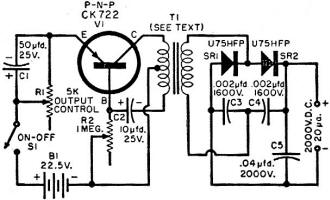
Fig. 4 - Transistorized high-voltage supply for Geiger and scintillation
counters.

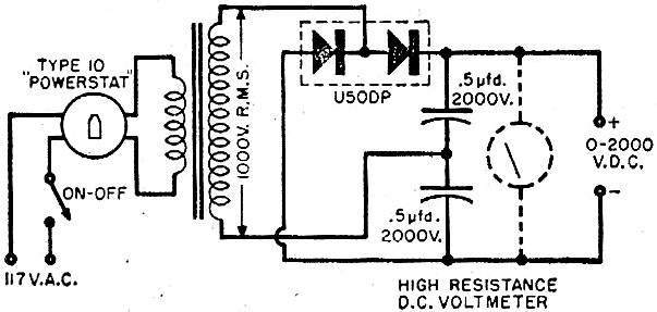
Fig. 5 - A general-purpose, variable, high-voltage, low-current
type power supply.
The d.c. output is 2000 volts at 20 microamperes. This is adequate for a sensitive
scintillation counter. The high turns-ratio midget transformer, T1, is
a special component, Type TC-673 (Cam-Co Engineering Company, Culver City, California).
The transistor oscillator is powered by a medium-sized 22 1/2 volt "B"-battery (Burgess
Z30NX, or equivalent). The low d.c. drain of 7 1/2 to 10 milliamperes insures long
battery life.
Efficient voltage doubling in the full-wave circuit is afforded by the two rectifier
cartridges. However, a dual rectifier unit, like the International Rectifier Type
U50DP, (Fig. 1D) may be used, if desired. For small over-all size, the electrolytic
capacitors, C1 and C2, may be of the subminiature tantalum
variety.
In adjusting the unit, the following steps should be observed. (1) With switch
S1 open, set rheostat R1 to its maximum resistance. (2) Connect
a high-resistance d.c. voltmeter (20,000 ohms-per-volt or higher) to the d.c. output
terminals and close switch S1. (3) Adjust rheostat R2 for
maximum voltage. (4) Lock R2 in this position and do not subsequently
disturb its setting. Make all later output voltage adjustments with rheostat R1.
This transistor oscillator is stable and is a good starter if the R1
and R2 adjustments have been made correctly. With the d.c. voltmeter
connected to the d.c. output terminals, the starting action may be checked by throwing
switch S1 rapidly back and forth several times. The voltage should rise
and fall quickly in response, within the limitations set by the meter damping.
Beside its specific use as the high-voltage d.c. supply for Geiger and scintillation
counters, this unit may be employed in other applications requiring a totally quiet,
battery-operated, portable source of 2 kv. or less. Such uses include photomultiplier
tube supply, voltmeter calibration, klystron electrode supply, portable oscilloscope
supply, etc.
Variable-Voltage Supply
Fig. 5 shows the circuit of a general-purpose, adjustable-output, low-current,
high-voltage supply which may be made as small as some test meters. The d.c. output
voltage is 0 to 2000 volts at a maximum current of 3 ma.
In this arrangement, the a.c. input voltage to the transformer may be varied
by means of a Superior Electric Type 10 "Powerstat." A General Radio 200B "Variac"
also may be used for this purpose. A full-wave voltage doubler is operated from
the high-voltage secondary of the transformer. The doubler consists of a Type U50DP
doubler type high-voltage selenium cartridge and the two 0.5 μfd., 2000 volt
capacitors.
Any convenient transformer having a 1000 volt r.m.s, secondary may be used. For
convenience and economy, the entire secondary winding of a small replacement type
transformer may be employed, neglecting the center tap of this winding.
At the low values of current drain specified, storage action of the two 0.5 μfd.
capacitors and the full-wave operation of the rectifier unit will smooth the d.c.
output well enough to permit use of the high-voltage output for the calibration
of d.c. voltmeters, polarization of cathode-ray and photo-multiplier tubes, dielectric
studies, radiation detector operation, and polarizing capacitors. However, additional
filter circuitry may be added externally or internally for discriminating applications.
A continuously variable supply of this type will find sundry uses in the laboratory
and shop. A prosaic application is the flash-burning of particles from between the
plates of variable capacitors.
An optional output-voltage indicating meter may be included in the completed
unit, as shown dotted in Fig. 5. This must be a high-resistance d.c. voltmeter of
at least 20,000 ohms-per-volt sensitivity.
Scope High-Voltage Supply
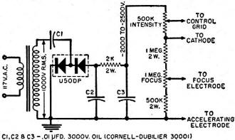
Fig. 6 - High-voltage supply for an o-scope.

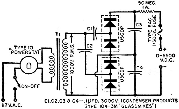
Fig. 7 - Schematic of an insulation tester.
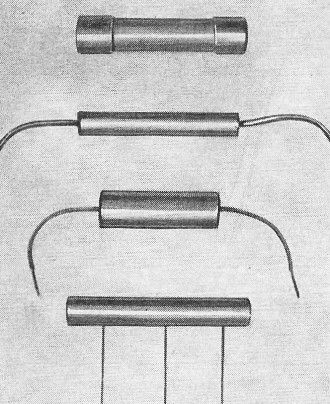
Fig. 8 - High-voltage selenium cartridges.
A selenium voltage multiplier circuit can simplify the high-voltage section of
a 5- or 7-inch oscilloscope power supply. Fig. 6 shows a circuit of this type complete
with focus and intensity controls.
A half-wave doubler is used so that a common ground may be employed throughout.
A Type U50DP doubler type cartridge is used. The voltage multiplier capacitors are
C1 and C2. Capacitor C3 provides additional filtering
action, operating in conjunction with the 2000 ohm filter resistor, since this circuit
is not as easily filtered as the full-wave doublers described previously.
The transformer may be a special half-wave unit having a 1000 volt, low-current
secondary. The entire secondary (both sides of center tap) of a low-voltage transformer
supplying the amplifier and sweep tubes in the oscilloscope may be employed under
some circumstances.
Insulation Tester
Another type of continuously variable, high-voltage d.c. supply is shown in Fig.
7. This setup has been designed primarily for insulation testing and other dielectric
breakdown measurements but may be used in any other application requiring an adjustable
low-current output up to 5500 volts d.c.
Smooth variation of the output voltage is obtained by adjusting the input voltage
to the transformer by means of a small (Type 10) Superior Electric "Powerstat."
A General Radio 200B "Variac" may also be employed for this purpose.
The transformer has a 1000 volt secondary. Its output voltage is presented to
a voltage quadrupler circuit composed of two U50DP doubler type selenium cartridges
and capacitors C1, C2, C3, and C4. The
d.c. output voltage is four times the peak value of the secondary r.m.s. voltage,
minus the drop in the rectifiers.
The 50-megohm resistor in series with the positive output terminal limits the
output current to 100 micro-amperes on external short circuit. The 8AG, 1/500 ampere
fuse has a blow point of 3 ma. and protects the rectifiers in the event of a sustained
external short circuit or overload.
A high-resistance d.c. voltmeter may be operated in parallel with the d.c. output
terminals to monitor the output voltage. Where the use of such a meter is not feasible,
however, the output voltage may be approximated from the measured value of a.c.
voltage at the transformer primary. The following expression may be used:
Edc = 5.65EiN. Here, Edc is the approximate
output voltage, Ei is the r.m.s. primary voltage, and N is the turns-ratio
of the transformer.
Conclusion
Possible uses of high-voltage selenium cartridges are multitudinous. Many other
types and sizes are available, four additional ones are shown in Fig. 8. We have
selected those applications about which information is constantly requested. These
are small-sized devices in which the elimination of tubes contributes lighter weight,
cooler operation, smaller size, simplicity of construction, and ease of servicing.
Reference1. Chambers, R. W. & Coleman, L. G.: "A High-Voltage
Transistor Power Supply," Radio & Television News, October 1955.
Posted September 30, 2020
|