|
Once World War II was over
and the peoples of the world could breathe and start enjoying life again, television,
which had just begun to take off before the war, quickly gained widespread adoption
in homes. As with so many areas of technology and science, advancements in electronics
and wireless communications during the war years redounded very beneficially to
the TV industry. Early schemes for television combined both electronics and mechanical
elements using rotating discs, vibrating mirrors, and other far-out schemes to convert
electrical signals to moving pictures. Due to the small size of the first cathode
ray tubes (CRTs), commonly called
kinescopes
at the time, light beams were launched toward physically maneuvered mirrors to steer
the image onto the back of a larger glass screen - basically the first projection
screen televisions ...but I digress. TV's popularity grew so fast in the late 1940s
and early 1950s that the Federal Communications commission (FCC) issued a moratorium
on the building of new broadcast stations until a scheme could be devised to deal
with signal overlap (interference) from too closely spaced stations. One solution
was to assign a new band above the original very high frequency (VHF) channel assignments
(channels 2-13,
what happened to channel 1?), which are the ultra high frequency (UHF) channels above channel
13. Many new technical problems quickly became apparent with UHF signals because
of the greater atmospheric attenuation rate of high frequencies (Friis equation), greater difficulty and expense
of higher frequency RF components, and the different kind of geophysical effects
of on the new band.
Developments in U.H.F.
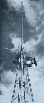
Receiving microwave dish antenna and high-gain channel 82 retransmitting
antenna shown on a u.h.f, satellite station tower.
By Edward M. Noll
Here are some new ideas to help you lick your u.h.f. reception problems; also,
new hope for u.h.f.'s future.
The problems of u.h.f. foretell the path it is to follow. What are the problems
of u.h.f.? There are three basic ones - coverage, economy, and sensitivity. Coverage
improvement is a most important consideration in modern u.h.f. operations. Any step
taken to improve coverage permits the serving of a greater populace with a more
reliable signal. The economies of u.h.f. operation have been baffling in many areas
because of the competition presented by strong v.h.f. signals and the fact that
many u.h.f. stations are located in smaller cities where the capital wealth is substantially
less than in large metropolitan areas.
Sensitivity has to do with the ability to make full use of whatever u.h.f. signal
strength exists at the receiving location. Sensitivity is best interpreted in terms
of signal-to-noise ratio. The over-all gain of a u.h.f. converter and a modern television
receiver is adequate to amplify even the very weakest u.h.f. signal. The problem
really is not one of lack of gain but rather of making the incoming u.h.f. signal
dominate the inherent noise in the u.h.f. device. A typical u.h.f. converter employs
a crystal mixer and a rather narrow-band i.f. stage following the mixer. Consequently
a very excellent signal-to-noise ratio can be established. Despite a good noise
factor the u.h.f. signal is so weak in many areas and at some sites quite close
to the transmitter, that it is not able to dominate the noise level.
It is apparent that the improvement in u.h.f. sensitivity must occur at some
place between the antenna and the u.h.f. mixer. A stronger u.h.f. signal must be
delivered to the u.h.f. device. At present, the use of u.h.f. radio frequency stages
is too costly if the vacuum tube amplifier is to be designed with a noise factor
better than that which can be attained with a crystal mixer. These factors stress
the important contribution that the technician must make in obtaining better u.h.f.
coverage. The u.h.f. antenna, transmission line, and installation are the key factors
in the delivery of a stronger u.h.f. signal to the mixer.
Sensitivity Improvement
We have indicated in the previous paragraphs that u.h.f. reception would be improved
most effectively if the signal level could be increased prior to its application
to the mixer. In the receiver system there is sufficient amplification after the
mixer. However, the major problem is to deliver a stronger initial u.h.f. signal
to the converter so that inherent noise levels might be better surmounted. Delivery
of a strong signal to the mixer depends on choosing the proper mounting position
for the antenna, using an efficient high-gain antenna, and minimizing the loss of
signal between the antenna and input to the u.h.f. device. A fourth consideration
in the over-all performance of the u.h.f. converter is the crystal mixer itself
as well as the local oscillator injection level. For best efficiency in a weak signal
area, the technician should be certain to have a peak-performing crystal and local
oscillator tube in the u.h.f. device. Comparison can be made by substitution.
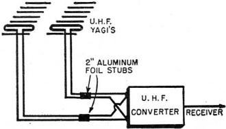
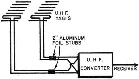
Fig. 1 - Diversity reception setup for using two u.h.f. antennas
with one converter or tuner. The small 2" aluminum stubs are used to maximize the
signal.

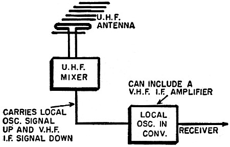
Fig. 2 - Mounting the mixer stage of a u.h.f. converter or tuner
on the antenna mast minimizes the loss of signal in the transmission line. This
loss is much greater for u.h.f. than for v.h.f.
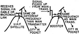
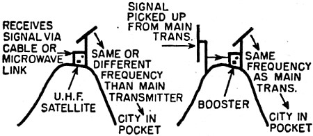
Fig. 3 - Satellite and booster stations are used as shown here
to fill in pockets of poor or no reception within the transmitter coverage area.
The booster rebroadcasts on the same frequency as that of the original signal; the
satellite station may broadcast on another.

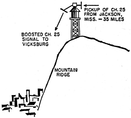
Fig. 4 - A booster station located on a water tower near Vicksburg,
Mississippi, fills in the channel 25 coverage area.
Using a higher gain u.h.f. antenna would be most helpful in raising the u.h.f.
signal level of a particular installation. However, the u.h.f. corner reflectors
and narrow-band yagis commonly used in low signal areas are already high-gain antenna
types. The degree of elaboration necessary to obtain a substantial improvement over
these types is prohibitive. In a practical sense, we have had more success with
diversity arrangements of u.h.f. antennas.
In a typical diversity arrangement for the reception of a single weak u.h.f.
channel, two narrow-band twelve-element yagis may be employed as shown in Fig. 1.
Each yagi is positioned in a strong field. (Although this is a very important consideration,
there is no definite equation that will permit you to calculate or estimate mounting
positions for maximum signal. The procedure is entirely experimental.) After a strong
signal position is found for each antenna, two separate lines are run down to the
u.h.f. device. As is required for a good u.h.f. installation, the line (low-loss)
should be run as direct as possible. The two lines are joined together at the input
to the u.h.f. device. However, each line must be tuned for peak signals. To do this,
proceed as follows:
1. Connect a transmission line from one of the u.h.f. antennas to the input of
the u.h.f. device. Wrap a two-inch piece of aluminum foil around the line and slide
the foil back along the line until a peak signal is obtained.
2. Touch the leads of the transmission line from the second antenna across the
input terminals of the u.h.f. unit. Notice if there is an increase or decrease in
signal level. If there is a decrease, reverse the leads. Fasten the leads beneath
the input terminals.
3. Wrap a two-inch piece of foil around the second transmission line and move
it for maximum signal. Re-adjust the foil on the first transmission line slightly
for maximum signal.
Another effective aid in improving u.h.f. reception is the positioning of the
u.h.f. mixer at the antenna. The u.h.f. local oscillator may be located at the same
point or down at the receiver. When the local oscillator is located indoors, near
the receiver, it is not necessary to supply any power to the antenna-mounted u.h.f.
mixer. The u.h.f. injection signal is sent up the transmission line from the local
oscillator as shown in Fig. 2. The local oscillator signal mixes with the u.h.f.
signal and sends a v.h.f. resultant down the line to the v.h.f. amplifier that is
a part of most converters.
The antenna-mounted u.h.f. mixer eliminates the severe loss of u.h.f. signal
strength that is caused by high attenuation at u.h.f. frequencies. This arrangement
is especially helpful when long lengths of line are required between the antenna
and receiver. Additional improvement can be obtained by locating a high-gain, low-noise
v.h.f. amplifier at the antenna to amplify the v.h.f. resultant before it is sent
down the line.
U.H.F. Coverage
The reliable coverage area of u.h.f. stations is being extended with the increase
in power output and proper location of the transmitting tower. A few stations with
effective radiated powers of one million watts expect to be on the air shortly.
Although increasing the effective radiated power by using a high gain antenna
is advantageous, it cannot be carried to the extreme. As the antenna gain is increased,
the vertical radiation pattern is more and more confined. With too narrow a vertical
radiation pattern it is possible to create pockets in the coverage area in which
there is no signal or a very weak signal. Consequently, it is also important to
increase the power output of the transmitter because in this way an increase in
effective radiated power can be obtained without confining the radiation pattern
too drastically.
Proper location for the transmitter site is very important. It is not always
advisable to locate the transmitter too far from and too high above the populated
area to be covered. In the desire to include more and more cities in the coverage
range, the transmitter is often located at too great a distance from the major area
to be served. This results in poor reception pockets in what is considered to be
the primary coverage area for the station.
Transmitting antenna height is also important. It is conceivable that with too
high an antenna location and too high an antenna gain, sections moderately near
to the station will be without coverage.
The satellite and booster stations have proven encouraging in filling in pockets
and extending coverage at reasonable cost. A booster station, as shown in Fig. 3,
picks up the transmitted signal from the main station at a point where the signal
intensity is still very high. The booster can be located on a mountain top near
the poor reception pocket or near the distant city to be covered. The received signal
is amplified and then re-radiated on the same frequency by a low-powered transmitter.
The booster transmitting antenna is made highly directional to concentrate the re-radiated
signal into the poor reception pocket. Because the high-gain antennas at the booster
station are highly directional, there is a minimum of interference between the direct
signal and the re-radiated one.
A successful installation of a booster station was made by RCA to supply Vicksburg,
Mississippi with a satisfactory u.h.f. signal from Jackson, Mississippi, some 35
miles away. Vicksburg, which is shadowed by a ridge, had not been able to receive
satisfactory signals from the 17,000 watt transmitter at Jackson. The high gain
receiving antenna, mounted on a water tower, as shown in Fig. 4, picks up the channel
25 u.h.f. signal from Jackson and applies it to a booster amplifier.
The gain of the booster is approximately 100 db with a bandwidth essentially
fiat over 6 megacycles. The output of the booster supplies signal to the highly
directional booster antenna that directs the channel 25 signal into the Vicksburg
area. To minimize interference between the two antenna systems and signals, the
antennas are designed with high gain and ideal patterns.
Another method that can be employed to minimize interference be-tween two signals
on the same frequency is to change the signal polarization. For example, it is possible
in a booster operation to receive a horizontally polarized signal from the main
station and apply the booster amplifier output to a vertically polarized transmitting
antenna. In this arrangement, the receiving antennas in the poor reception pocket
area must be vertically polarized.
Economics of U.H.F.
The economic problems of u.h.f. have been trying. Most allocations have been
to small cities which have limited sources for station revenues. In many areas the
u.h.f. station has to compete with a local v.h.f. station or with a v.h.f. fringe
station that delivers adequate signals to the area. The growth of u.h.f. is further
hampered by limited coverage and the fact that an investment is required on the
part of the viewer to add u.h.f. reception to his receiver. The additional equipment
needed to extend coverage and increase power is a further burden on the u.h.f. station.
In a number of locations local u.h.f. stations have suffered because of competition
from community wired-television systems.
Certainly u.h.f. is here to stay. It delivers, and will continue to deliver,
reliable service within its coverage limitations. We can expect to find continued
developments both in trans-mitting and receiving methods to im--prove reception
conditions within the projected service areas of u.h.f. sta-tions. However, the
rate of growth and the total number of u.h.f. stations to come on the air must now
be esti-mated more conservatively because of the problems discussed here.
Posted March 5, 2020
|