|
In the early days of television,
what we today refer to as cathode ray tubes were called kinescopes. The kinescope
on the receiving end displayed images generated by a tube called an
iconoscope
on the transmission end. Kinescopes had round faces onto which a rectangular picture
was electronically drawn. Once manufacturing technology evolved sufficiently, it
became possible to make them rectangular in order to save on material and to fit
a larger picture in a smaller area. The real story as told in this 1947
Radio News magazine article from my perspective
is appreciating the ingenuity of the manufacturing engineers for an ability to develop
machines that handle very complex operations. They were wonders of electromechanical
manipulation. There were still some operations that needed human dexterity and decision
making. Oh, and I learned a new word - "lehr" - which is an oven used
to anneal glass.
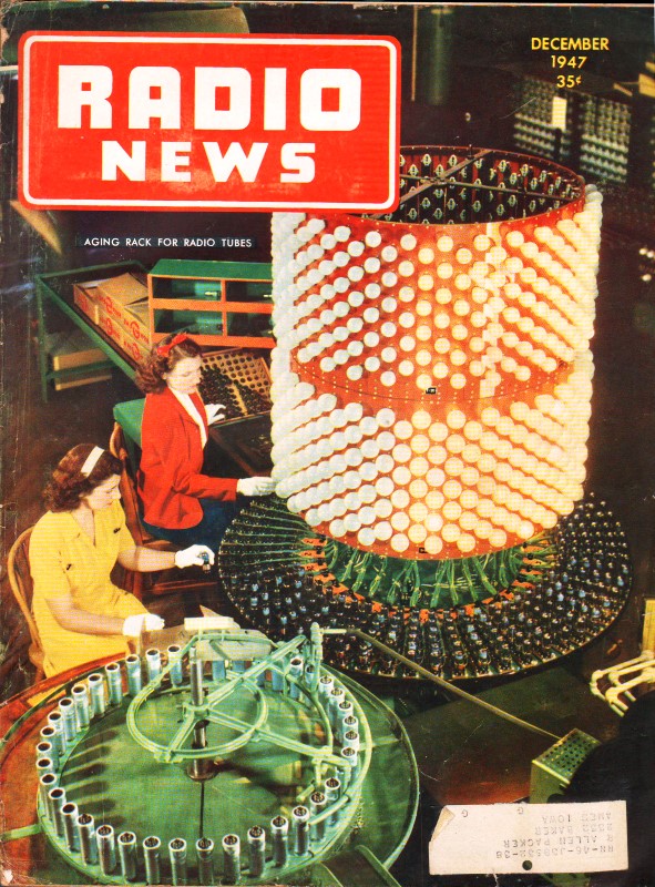
Television Tubes by the Thousands
By Frank E. Butler
Fig. 1 - Completed 10" kinescope at left. Center unit
is bulb blank in which the "button" has been sealed. In front of tube are the stem
and completed tube element assembly. Right hand bulb shows fluorescent coaling and
colloidal graphite lining.

Fig. 2 - Flare machine in which G12 glass tubing is cut
off and pre-formed to provide a flat pressed stem for the tube. Glass parts are
heated at various stages from 600-90°C.

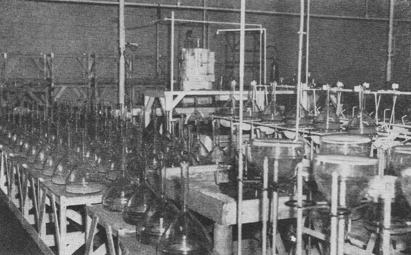
Fig. 3 - Hundreds of 10-inch kinescope bulbs lined up ready
for the application of the fluorescent coating to the inside. .Each tube receives
a measured amount of solution.
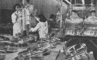
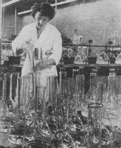
Fig. 4 - Operators prepare the fluorescent solution which
is used in the kinescopes to form the picture screen of the video tube. Quality
control of the solution is vitally important here.

Fig. 5 - Fluorescent coating, in solution, is carefully
poured into a prepared kinescope bulb.
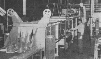
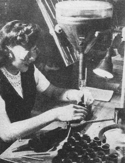
Fig. 6 - Next step is the insertion of the "button" in the
side of the bulb by means of a gas-fired torch. Operator softens the glass, punctures
a hole, and inserts button.

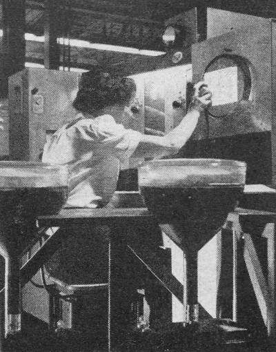
Fig. 7 - Baking on the colloidal graphite coaling requires
approximately one and a half hours at 400°C in a gas-fired oven. A specially
designed oven is used in this operation.
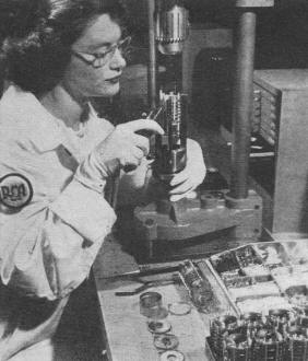
Fig. 8 - A non-reflective carbon coating, designed to keep
stray electrons from the picture screen, is next applied with a long-handled brush.
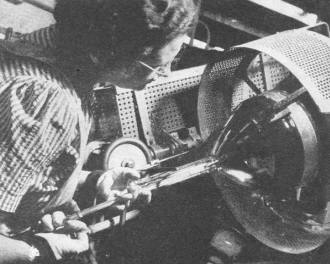
Fig. 9 - The operator is shown installing the cathode-ray
gun in a modern type image orthicon camera tube which is used for video pickups.

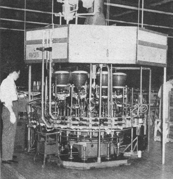
Fig. 10 - Automatic sealing machine where elements are set
in tube. The flare and bulb are sealed and the collet is cut off.

Fig. 11 - Close-up view of operation in which collet is
cut off. The gas burner shown at right performs the annealing operation.

Fig. 12 - Operator threads lead-in wires into socket base
of a kinescope after the air has been exhausted from the tube envelope.

Fig. 13 - Technician checking kinescope picture tubes during
a 500-hour continuous performance test run at the home plant.
A modern miracle of mass production is typified by the ingenious wedding of automatic
machinery, technical skills, and quality-controlled materials.
The Age of television is at hand and to speed its progress toward perfection,
groups of technical experts in widely divergent professions such as electronics,
optics, and the glass industries are contributing their share of scientific knowledge
and experience to this end.
The technological advance is so rapid, both in monochrome and color television
transmission and receiving equipment, that pictures by both systems are now being
shown with surprising realism and clarity. Only very little of this advanced development
remains in the laboratory stage and this is sufficiently developed to insure its
appearance in homes much sooner than most of us had expected.
The rapidity and skill with which this progress has been made by television laboratories
and their confidence in the future of television is evidenced by the building of
new plants and the designing of special machinery for the manufacture of equipment.
Therefore a peep behind the scenes of television activity should prove of unusual
interest at this time.
The heart of television is the iconoscope - the electronic device capable of
detecting the image or scene of action that is to be televised through space, then
subsequently translating the reflected light into electric impulses.
The kinescope is a similar electronic tube which reverses the above action whereby
the televised impressions are transformed back into light to form a reproduced image
or "picture" on the sensitive face of the tube. To create these two companion tubes,
which must combine delicateness, ruggedness, and utmost sensitivity, requires the
use of nimble fingers, keen eyes, highly developed skills, modern automatic machinery
and the best techniques that can be devised by the several different industries
involved in the manufacture of tubes.
The factory where these tubes are . produced must be fully air conditioned and
the humidity level must be maintained at a predetermined level. In addition, the
factory must also be equipped with dust filters in order to eliminate impurities
which might affect the sensitive tube elements.
There are two kinds of kinescopes produced - one known as the electronic direct
view type, and the other as the projection type. From the small kinescope which
produces exceptionally brilliant images which are subsequently enlarged optically
for projection on a viewing screen of a 7 1/2 x 10 or 18 x 24 foot theater size,
to the largest kinescopes which have a 10 or 12 inch face from which the image is
viewed directly (without enlargement), there are many precise and intricate operations
which must be performed on both the tube elements and the glass bulb.
One of the first glass operations in the production of kinescopes or iconoscopes
is to make the flare of the stem which holds the elements. This is done on the flare
machine shown in Fig. 2. Here gas fuel is used to heat the glass parts as
they index around the automatic machine, in various stages, to temperatures rangng
from 600°C. to 900°C. After a small section has been cut off and the end
flared, the bottom portion is heated by a special gas flame pattern which places
the heat exactly where it is wanted at the proper temperature for flat pressing.
Heating time is controlled by the speed at which the machine indexes from station
to station.
A battery of automatic flare machines is used in making the glass stems in which
the tube element supporting the lead-in wires are sealed. Specially designed gas
burners, emitting predetermined flame patterns heat the glass tubing to various
stages of viscosity in order that it may be flat pressed into a stem. All of the
equipment that utilizes heat in any form for processing is efficiently hooded and
ventilated to carry off excess heat and the products of combustion.
When this part has been formed, the lead-in wires to the tube elements are inserted
and the assembled element units are placed on another automatic gas-fired machine
where special flame patterns heat those parts of the stem to just the proper temperature
and for just the correct time to effectively seal the wires into the glass stem.
Annealing takes place immediately after the part has reached the last position on
the machine. The unit is then ready for mounting the tube electrodes, after which
it is prepared to be sealed into a bulb-blank, which resembles a large glass funnel
with a long stem.
The bulb or kinescope blanks are subjected to many processes and operations;
the first being a thorough washing, inside and out, after which they are placed
in specially constructed racks in the "settling-room" Fig. 3. This room is
constructed on its own foundation and the floor is composed of a heavy concrete
slab floating on a layer of cork. There is no physical connection to any other part
of the building, thus eliminating any transmission of vibration. A measured quantity
of liquid containing a fluorescent substance is then placed in each tube. The preparation
of this fluorescent solution requires a high degree of skill and accuracy. The operation
is shown in Fig. 4.
Next, the coating, in suspension, is carefully and accurately poured into the
kinescope bulb. See Fig. 5. Slowly, the solid, active fluorescent material
settles on that part of the tube face on which the electrons react to produce the
image. When the settling process is complete, the remaining liquid is carefully
decanted.
The next step in the manufacture of the tube is the insertion of a "button" in
the side of the bulb. This operation, which is illustrated in Fig. 6, is performed
by means of a gas-fired torch. The operator softens the glass, punctures a small
hole and inserts the "button" or electrical contact which is then hermetically sealed
in the tapered section of the bulb. The tube is then annealed at 450°C. by means
of a continuous gas-fired radiant tube glass lehr where the cycle of passing through
the heated air ranges from four to six hours, depending on the size of the tube.
The inside of the bulb is next coated with a colloidal graphite mixture which
serves to carry off the electron charges after they bounce back from the screen.
The grounded electrical circuit is through the "button" previously described. Next,
this inner graphite coating is subjected to a baking cycle which is performed at
temperatures of 400°C. for approximately one and a half hours. This operation
is shown in Fig. 7.
The operator now applies a coating of non-reflecting carbon to the interior of
the tube by means of a long handled brush (See Fig. 8). This coating keeps
stray electrons from the picture screen.
Fig. 9 shows the operator adjusting the delicate electrical components that
are to be inserted in the tube. At this stage of production, the prepared bulb is
ready to be sealed to the glass stem which supports the internal elements, or electron
gun. This operation takes place on a completely automatic gas-fired sealing machine
(Fig. 10) where the elements are set in the tube, the flare and bulb are sealed,
and the collet cut off. These operations take place as the tubes index around the
machine to their respective stations where varying patterns of gas flames perform
the successive operations on the glass. At the final station the excess neck of
the bulb, or collet, is cut off when the No. 6 lime glass of which the kinescope
blanks are made is heated to 1050°C. by a needle flame which produces a clean,
sharp cut.
Fig. 11 shows a close-up view of the six needle gas flames which concentrate
on the bulb neck where the collet is cut off as the tube revolves in the flame.
The large gas burner, shown at the right of the photograph, performs the annealing
operation. When the vacuum process has reached its final position, the tube is "tipped
off" - an operation w h i c h seals the tube permanently and severs its connection
to the vacuum pump.
After sealing, the tube progresses to an exhaust machine where an extremely high
vacuum is developed. While on this machine, the glass bulb is heated by radiant
heaters to its softening point to assist the vacuum pump in removing occluded moisture
and gases. The electron gun and other internal elements are heated by high frequency
induction methods and, at another stage in the process, working voltages are applied
to the tube elements themselves.
After the tube has been evacuated and severed from the exhaust machine, the operator
threads the lead-in wires into the socket base of the kinescope. This operation
is shown in Fig. 12.
Final tests are then run on the complete kinescopes. The operator (Fig. 14)
uses a special chart as a reference standard. Following this testing, the tubes
undergo a 500-hour operational test (Fig. 13).
Larger television pictures obtainable in the projection system are the result
of an optical development which is an outgrowth of a discovery revealed in 1932
by Bernard Schmidt, a research assistant in a German laboratory. At that time astronomical
photography was unsatisfactory, due to spherical aberrations caused by the mirror
used to reflect light from the stars and planets to the camera. By placing a "correcting
lens" (corrector plate) between the mirror and the camera, Schmidt discovered that
he obtained much clearer pictures. These plates, however, had to be ground by hand,
and prior to the war there were only a few in existence because of the extreme difficulty
of their manufacture. During the war, American scientists developed a new method
for mass producing these "corrector plates" which were used in infrared viewing
devices. Now, tens of thousands of these plates, embodying the same technique are
being used for television reception. They are made by heating a flat piece of glass
until it flows into the specially curved surface of a refractory on which the glass
is placed. This mold is made of special composition that does not adhere to the
glass and yet permits it to assume the desired curvature. One side of the glass
is then ground and polished to a plane surface.
The mirror is aluminized in such a way that the reflectivity will be as high
as possible. The problem of aluminizing large surfaces and producing an aluminum
surface of the required durability was not simple, but it was solved .
Another contribution to the development of television receiving sets was the
result of a war-time invention for producing glareless glass. This process makes
possible the reception of clearer, sharper television pictures. The successful removal
of light-consuming reflections from a television tube's glass face, which serves
as the screen of a direct-viewing home television receiver, has been obtained through
a new glare-removal technique which also produces images of greater clarity when
applied to the optical system of the projection type. The technique was developed
during the war to increase the efficiency of such military optical instruments as
binoculars which gained over 60 percent in light transmission when reflections were
reduced. Reflections are removed by directly coating the face of the television
tube with a secret chemical composition. It is not necessary to disassemble the
tube for the coating process or to apply the coating in the vacuum chambers used
in earlier glare-removing techniques.

Fig. 14 - One of the test procedures used in checking the performance of
kinescopes used in home television receiving sets.
The coating improves the reception of television pictures by: (1) Reducing reflections
in the glass face of the tube caused by light sources in the room housing the receiver.
(2) Reducing the intensity of false images caused by reflections from the outer
surface of the image-producing fluorescent screen in the tube, thus increasing the
sharpness of the images. (3) Reducing light losses from reflections, thus increasing
the amount of light transmitted.
It is a tribute to glass craftsmen, machine designers, optical technicians, skilled
operators, and electronic engineers that these relatively high temperatures, automatic
operations, accurate optical amplification, and extreme electronic sensitivity can
be used effectively in such narrow confines as the interior of television tubes
- the iconoscope and the kinescope - an accomplishment which has been due to the
efforts of these men of vision and still working in close cooperation.
Color and Monochrome (B&W) Television
Articles
Posted August 1, 2022
(updated from original post on 9/8/2015)
|