|
This seventh installment in an
eleven-part series on "Theory and Application of U.H.F." appeared in the October
1944 issue of Radio News magazine. Author Milton Kiver covered a wide range
of topics including basic and advanced circuits, tube types, modulation, resonant
cavities, oscillators, transmission lines, waveguides, antennas, electromagnetic
fields, and Maxwell's equations. Part 7 continued the discussion of how waveguides,
both rectangular and circular, support the conduction of electromagnetic waves.
Methods for injecting and extracting signals is covered as well. Interestingly,
the Smith chart never appeared
even though Phillip H. Smith had introduced it around 1936. In fact, the first
mention of the Smith Chart in Radio News, per a WWW search, was in 1950.
Eleven installments appeared in the following issues: Part 1: December 1943
(p35), 2: January 1944 (p32), 3: March 1944 (p41), 4: April 1944 (p46),
5: May 1944 (p50), 6: August 1944 (p53), 7:
October 1944
(p58), 8: December 1944 (56), 8: February 1945 (p58), 10: April
1945 (p57), 11: June
1945 (p57). I hope to eventually procure those editions and post the articles.
Part 7. Additional properties of wave guides used as a means of transmitting
energy at the ultra-high frequencies.
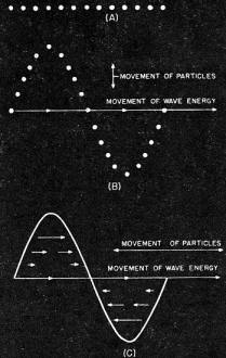
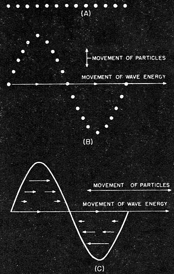
Fig. 1 - Illustrating the variation between transverse and longitudinal
waves. (A) No wave motion. particles are at rest. (B) Transverse wave, particles
vibrate up and down while the wave energy moves forward. (C) Longitudinal wave particles
move back and forth while wave energy moves forward. Length of arrows in (C) indicates
relative distance of particle movements.
By Milton S. Kiver
In the August issue of Radio News the fundamental ideas concerning wave guides
and the electromagnetic waves that flow along these guides were presented. As stated,
a wave guide merely confines the radio waves that ordinarily would flow uncontrolled
in three-dimensional space. The method of starting these waves off is very much
like our ordinary every-day processes with which all are so familiar. An antenna,
in this case the inner conductor of a coaxial cable, is placed inside a guide and
from this emanates the electromagnetic energy. By a series of reflections off the
restricting walls of the guide, the energy is propagated down the guide to whatever
use may be made of it. The end may be open, in which case the energy flows out into
free space, or the receiving antenna may be placed here to pick up this energy.
The final property of a guide, mentioned in the last article, concerns the action
of this wave guide in allowing waves of certain frequencies to be propagated down
the guide, while others of a lower frequency are stopped, so to speak, at the very
mouth of the guide. This selective effect, or filtering action, may be useful if
only certain waves are desired to the exclusion of others of lower frequency. Note
that this action is comparable to that of a high-pass filter in ordinary radio or
electrical circuits. Keep in mind throughout this entire wave guide discussion that
these guides are used for the very simple reason that they attenuate the high frequencies
less than any coaxial cable devised so far. It is entirely permissible to think
of these guides as transmission lines specifically designed for the ultra-highs,
and, indeed many writers do.
Up to this time the types of waves merely have been mentioned without taking
time out to explain the system used in arriving at these peculiar looking symbols.
It might be best to start at the beginning and explain the difference between a
transverse and a longitudinal wave which will lead more directly to the desired
results. To demonstrate longitudinal wave motion take an ordinary tuning fork and
hit it sharply, causing it to vibrate back and forth. This motion will force the
molecules nearest the tuning fork to vibrate back and forth, and the resultant waves
will travel outward in all directions. The vibration of the molecules, in this case,
is in the same direction as the propagation of the sound waves thus causing their
paths to be parallel. This is the defining characteristic of a longitudinal wave.
It should, of course, be remembered that the molecules vibrate about a mean point
while only the energy is expanding outward. It is somewhat analogous to a situation
where a straight row of billiard balls is tapped at one end. The energy is transmitted
forward by the balls while the balls themselves remain fixed.
For the case of a transverse wave, consider the motion set up by water waves
that is caused by a small pebble dropped into a pond. The waves travel outward while
the small water molecules move up and down or at right angles to the direction of
propagation of the wave. Another example of this type of wave motion is illustrated
by the action of a rope, one end being secured and the other end moved up and down
by hand. Fig. 1 emphasizes the difference between the two types of waves pictorially.

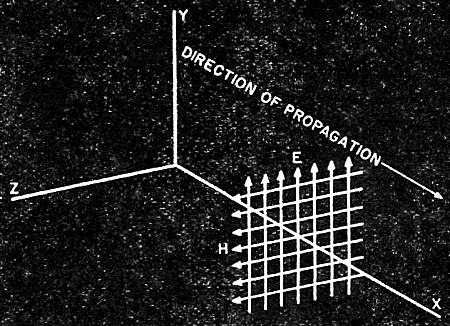
Fig. 2 - Rectangular wave guide showing the three separate axes,
x, y. and z.

Fig. 3 - An electromagnetic wave in a plane propagated along
axis X. Arrowed lines E signify electric lines of force, while those of H signify
magnetic lines of force.
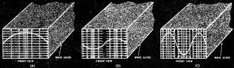
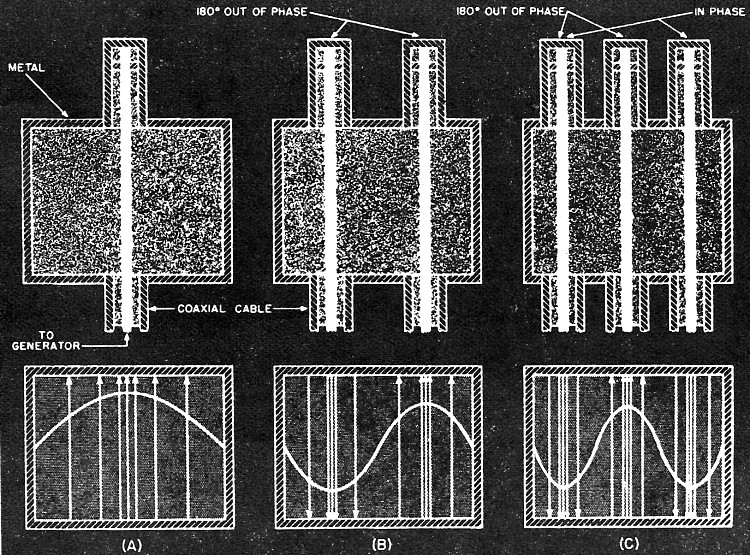
Fig. 4 - Three wave guides, all of the same dimensions showing
the changes in electric and magnetic field strengths as a result of increasing frequency.
Solid lines indicate electric field while dotted lines indicate magnetic field.
(A) TE0,1 wave. (B) TE0,2 wave. (C) TE0,3 wave.
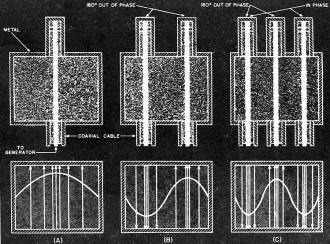
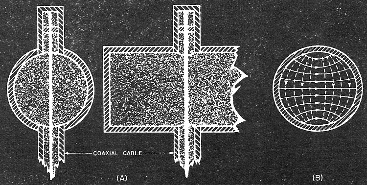
Fig. 5 - Methods of exciting wave guides to obtain the wave patterns
illustrated.
Changing from water waves and sound waves to electromagnetic vibrations, it can
now be shown how the preceding information can be used to label the various types
of waves in rectangular guides. As mentioned before, every electromagnetic wave
may have electric and magnetic fields with components along any of the three conventional
directions, namely, x, y and z (see Fig. 2). Suppose a wave had a magnetic field
along the z axis (Fig. 2) but no electric field in this direction. The electric
components could be either in the x or the y direction or both. Since the direction
of propagation of the wave is in the z direction, it can readily be seen that as
far as the magnetic field is concerned, since it has a component in the z direction,
this is a longitudinal wave. The necessary conditions as just defined at the beginning
of this paragraph are satisfied. However, since the electric field has no components
in the z direction, but only in the x or y directions, it can be called a transverse
wave. This also follows from the definition of transverse waves. Thus, there is
a choice. With regard to the magnetic field it is a longitudinal wave whereas with
respect to the electric field it is a transverse wave. The custom has been to label
the wave after the transverse component, so in this case the notation would be T
E, standing, of course, for transverse electric. Another notation sometimes used
is H waves.
To reverse the situation, let there be an electric field component along the
direction of propagation, the z axis, but no component of the magnetic field. The
latter will be confined to either the x direction, the y direction or both. .(It
has not been mentioned recently, but it will be recalled that the electric and magnetic
fields must be at right angles to each other so that it is not possible to have
a magnetic and an electric field along the same direction.) In this case there would
be a longitudinal wave with respect to the electric field and a transverse vibration
with respect to the magnetic field. Retaining the usual notation of labeling the
wave after the transverse component, will give, for this wave, the name T M wave.
The T M is an abbreviation for transverse magnetic. Another name that is sometimes
used is E waves. Having taken care of the two main cases a third and final type
of wave might be mentioned, which is in reality a plane wave (see Fig. 3). Here
the electric and magnetic fields are at right angles to each other and at the same
time are perpendicular to the direction of propagation. This can truly be called
a transverse wave for here there are no longitudinal components. The name given
this type of wave is a combination of the former two types and is TEM.
So far the nomenclature has been general, indicating only the class of waves
in operation but we still lack a specific notation that would point out which particular
wave in any group is being dealt with. In order to bring this out more clearly refer
to Fig. 4 where three types of waves in the TE class are shown. The simplest wave
in this group is shown in Fig. 4(A), where it can be seen that the dimension x is
just wide enough to accommodate a half wave of the electric field. In Fig. 4(B)
the frequency of the wave has been raised, so that now the same dimension x can
accommodate a full wave. In Fig. 4(C) the frequency has again been increased and
now we have three half waves. This process can be kept up as high as the frequencies
can be generated and each wave is differentiated from the other by a small subscript
n. Thus the lowest frequency waves, Fig. 4(A), would be represented by having n
equal to 1, Fig. 4(B) would have an n of 2, Fig. 4(C) would have an n of 3, etc.
The nomenclature is now more specific than it was before and is written as TEn.
But there is no reason why the dimension in the y direction should be ignored
since it is possible to have a variation in the electric field in that direction
also. In this case, use the subscript m and call each half wave of variation in
this direction 1. So finally the general notation is TEm, n and specifically
the wave in Fig. 4(A) is TE0,1 that in Fig. 4(B) is TE0,2
etc. Zero is used for m because there is no variation in the electric field in the
y dimension, but let it not be forgotten that waves like TE1,1, TE2,1
etc. are perfectly possible. They are not frequently mentioned because of the extremely
high frequencies involved, which for the present at least, are not easily generated.
And whatever has been said about the subscripts m and n are equally applicable to
the TM type of waves.
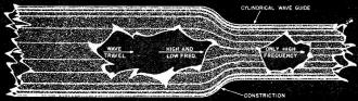
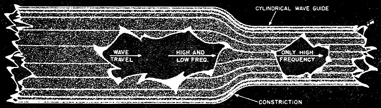
Fig. 6 - Filtering action of a cylindrical (or rectangular) waveguide
to separate two frequencies. The lower freq. is lost as the wave enters the smaller
portion of the guide.
The discussion of wave guides has progressed far enough so that it is now possible
to investigate the various methods used to excite these guides and get the different
types of waves mentioned. Excitation was only vaguely referred to previously when
it was merely stated that an antenna was placed in the guide and the electromagnetic
waves radiated from it. Each general type of wave (both TE and TM) and each specific
wave requires a different setup to produce the desired field patterns. However,
the similarity between the various waves of the TE group will be readily evident
and the same holds for the TM group. The generator will be omitted in each case
showing only the concentric cable placement in the wave guide but the obvious connection
of the cable to the generator should be understood. The simplest wave of the TE
group, namely TE0,1 can be generated by the type of arrangement shown
in Fig. 5 (A). The electric field pattern is shown underneath so that a mental connection
between the two can be formed. The TE0,2 wave can be produced by the
arrangement shown in Fig. 5(B). Since the exciting rods are 180° out of phase,
the electric fields are shown as being in opposite directions. The closer the lines
of force are, the stronger the electric field. As stated before, the intensity at
the sides of the wave guide must be zero and this condition is adhered to here.
The case of the TE0,3 wave is also shown and follows quite naturally,
Fig. 5(C). Note that it is the inner conductor that is connected from the generator.
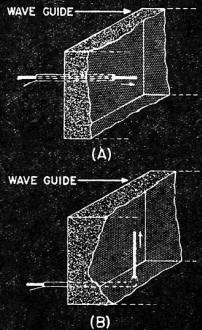
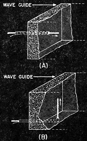
Fig. 7 - Two methods of exciting wave guides. (A) TM type wave.
(B) TE type wave.
To produce the fields for the TM type of wave, a setup similar to that shown
in Fig. 7(B) for the TE wave is used except for the position of the antenna in the
wave guide. For comparison, methods of producing both the TE and TM fields are shown
together in Fig. 7. In general, for the TEm,n type of wave, the antenna
will be at right angles to the direction of propagation while- in the TMm,n
case, these antennas are parallel to the direction of propagation. This is logical
since as previously pointed out, the TE wave has no electric field in the forward
direction while the TM wave has. It is only natural, then, that the placement of
the radiators should also differ by 90°. Provision is also usually made whereby
the length of the antenna in the wave guide can be adjusted to give best results.
This is an important adjustment since the measured intensity of the transmitted
wave may vary quite a bit between the best condition and the worst. Another adjustment
that is important is the distance between the antenna and the end of the wave guide
nearest it which acts as a reflector or backboard. The correct alignment can greatly
improve the transmitting efficiency. And while only the transmission has been discussed
here, every radio man knows that a good transmitting antenna is also an excellent
receiving antenna and so the results work both ways. In the case of reception, however,
the coaxial cable from the antenna is connected to a crystal detector which rectifies
the received current and thus makes it available for further use. Incident-ally,
these antennas when used for reception are pretty selective and will pick out one
type of wave almost to the exclusion of all others. By having several types of transmitting
antennas placed in various positions and at the other end of the guide receiving
rods in similar positions, the guide can be used for multiple channel transmission.
This is a point that will probably be of good use in days to come.
The reader may be a little confused by all the different types of waves that
have been explained. A question might naturally arise in his mind as to the reason
for having so many different modes of operation. The answer lies in the frequency
that is to be transmitted down the guide. For low frequencies, where there is only
one standing half wave across the mouth of the guide, a simple type of electromagnetic
wave may be used, such as the TE0,1. As the frequency is raised, the
number of half waves likewise increase and so the wave becomes more and more complex.
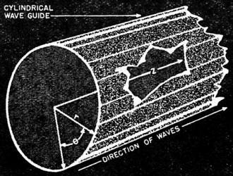
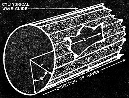
Fig. 8 - Cylindrical wave guide showing direction of wave and
various coordinates.

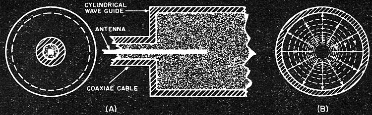
Fig. 9 - (A) Method of exciting a cylindrical wave guide to obtain
a TM0,1 type of wave. (B) Electric and magnetic lines of force set up
for this type of wave.

Fig. 10 - Method of exciting a cylindrical wave guide to obtain
a TE1,1 type of wave. Compare this with Fig. 9 and note the 90° change
in antenna position.
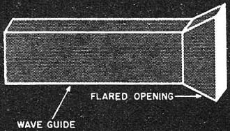
Fig. 11 - An electromagnetic horn.
Each of these complex waves may be looked upon as combinations of simple types
and they must observe the same general rules that apply to all electromagnetic radiations.
Another reason for studying these different type waves lies in the fact that some
have properties that may be of more use to us than those of other waves. Some may
be easier to generate and send, while others may not suffer attenuation as they
travel down the wave guides. Then, of course, there is the question of size. Higher
frequency waves require smaller guides than those of the lower frequencies. However;
the lower frequencies are easier to generate. Hence we arrive at a situation that
is not unlike what we have today. Some people prefer one type of circuit over another
and for each the reasons advanced are the best solution to the problem. As more
and more uses of the ultra-high frequencies are found there probably will be greater
simplicity and only a few types of waves will be used. But for a field that is just
in its first stages, everything connected with it comes under the engineer's microscope.
It is only by this process of experimentation that better and easier working models
are achieved.
The only wave guide discussed so far has been the rectangular wave guide, and
this was used because it is easier to visualize the actions of the electromagnetic
wave. However, there are other forms that these guides can assume, most of them
being of little practical importance, except the cylindrical wave guides. As with
the rectangular forms, it is possible to use the two notations (TEm,n
and TMm,n) to label the various types of waves that can be propagated
down the length of the tube, provided the frequencies used are not too low for a
particular diameter of the guide. The same conditions pertaining to electric and
magnetic fields still hold true even if the shape of these fields has changed. In
fact, the change is due to the difference in shape of the guide.
Usually, when dealing with these cylindrical wave guides, the geometrical notation
is changed from that used with the rectangular guides. This is illustrated in Fig,
8 for a cylindrical guide. Note that the, axis in the direction of propagation is
left the same, the changes occurring where we previously used the x and y axis.
Instead of these, we now deal with the radius
r and the angle B which allows us to go any distance from the central axis and
also to rotate through the complete 360° about this axis. Electric or magnetic
fields having components along any of these directions are differentiated from each
other by subscripts. Thus Ez means an electric field component in the
z direction, Er pertains to the radial direction and Eθ tells of
any field in the circular path. The same, of course, holds for the magnetic field
components.
For excitation of perhaps the TM0,1 wave in cylindrical guides, it
is possible to use a setup as pictured in Fig. 9(A). The resulting field pattern
is shown in Fig, 9(B), the view being an end one. Having only transverse components
of the electric field, the TE1,1 type depicted in Fig. 10 is obtained
and its method of excitation is included for those who might be curious. The critical
or cut-off frequency is higher for the TM0,1 wave than it is for the
TE1,1 wave, identical diameters being used in each case. This can be
easily seen when the formulas are given:
EQUATIONS HERE
for the TE1,1 wave. Note that due to the inverse relationship of the
frequency to the radius, a higher cut-off frequency requires a smaller opening of
the cylinder. Remember again that this frequency represents the lowest frequency
(or longest wavelength) that will be propagated down the tube without too much attenuation.
Practically, it is possible to transmit below this frequency but the range is rather
limited. Theoretically, all higher wavelengths can be easily transmitted without
much attenuation (using actual conductors), but in practice the upper frequencies
begin to show excessive attenuation because of increased skin effect. In between
these two extremes can usually be found a frequency that will have least attenuation.
Whether or not it is used will be determined by other factors that may assume greater
importance than attenuation.
It is now possible, since the action of a wave guide has been described in some
detail, to study some of the uses that have been evolved for wave guides. First
and foremost is its most important use, that of carrying ultra-high frequency power
from one circuit to another. The wave guide is essentially a transmission line which
has been modified for the very high frequencies and its extensive use is due to
the low loss or small attenuation introduced. What attenuation there is results
from the fact that the walls of the guide are not perfect conductors.
Some readers may resent the fact that it has been mentioned several times that
imperfect conducting walls will result in power losses and yet, no explanation has
been advanced which would prove or explain this. The explanation can be found quite
easily, but only if the investigator is equipped with a good knowledge of electric
and magnetic fields and also the differential equations developed by Maxwell. Since
only an elementary knowledge of mathematics has been assumed throughout this series,
all complicated. expressions have been omitted.
Continuing on, another use for the wave guide is possible, that of a high pass
filter. This property is connected with the action of a guide in allowing only frequencies
that are above a certain minimum value, which is known as the cut-off frequency,
to pass and all lower values to be rejected. This effect does not necessarily have
to take place at the opening of the guide; it may occur anywhere along its length.
Fig. 6 illustrates what is meant. The first section of the pipe has a certain diameter
which becomes less after the constriction. Waves that could be propagated in the
first half might not continue on after the diameter has been decreased and would
thus be attenuated or reflected, probably both. The point, however, is that they
would not continue on in the latter portion of the pipe. In this way frequencies
may be separated, an action that can only be brought about at lower frequencies
by coils and condensers. In fact, the analogy to filter circuits can be extended
even further by combining sections of wave guides that have different filtering
characteristics.
Another use that will be mentioned briefly here (but to be described later in
greater detail) is the cavity resonator which can be considered as a section of
a wave guide. Just as it was possible to take a small portion of an ordinary transmission
line and convert it into a resonant circuit, so is it possible to close one end
of a small section of a wave guide and get the same results, only at much higher
frequencies. The transition of the tuned circuit can be pictured as starting out
at the low frequencies with a coil and condenser, becoming a section of a transmission
line at the hyper frequencies and then finally ending as a cavity resonator at the
ultra-high frequencies. The function still remains the same, the means for accomplishing
this end being varied.
The final use to be considered will also be gone into in greater detail in another
chapter and concerns itself with the action of a wave guide as an antenna. The wave
will travel down a wave guide without reflection of any of its energy just as long
as no changes occur in the guide itself. This is equally true in any transmission
line. However, should any change occur, such as a solid wall or constriction in
the guide, it immediately results in a reflection of energy back along the guide.
For transmitting purposes, the open end is of most importance. Some of the energy
hitting this open end will continue out into free space while some of it will be
sent back. However, if the change is not made very abruptly, but rather is introduced
gradually, then the amount of energy sent back (or reflected) will be less and the
forward transmitting efficiency of the wave guide will increase appreciably.
This flared type of guide (Fig. 11) is known as an electromagnetic horn and has
very definite directional properties. It will be considered in greater detail along
with other types of ultra-high frequency antennas to be taken up presently. Here
the flare is a gradual change in the wave guide which allows more of the wave to
be sent forward and less reflected hack. (To be continued in
December issue)
Posted April 8, 2021
|