|
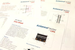
A white paper has been published by Linx Technologies titled, "How to Understand an Antenna Data Sheet." Author, Shawn Hogan, VP of Engineering,
writes, "The information on an antenna data sheet is nothing short of overwhelming. It can
be difficult to maneuver through to select the best antenna for your design. There are several
factors to take into account when looking at an antenna data sheet including: monopole vs.
dipole antennas, the electrical parameters, counterpoise, gain and radiation pattern. Our
goal is to break down these features so you can use that knowledge to discover advantages
and disadvantages of different antennas as they relate to your specific application..."
This article is an entry in Linx's new Blog.
How to Understand an Antenna Data Sheet
 The information
on an antenna data sheet is nothing short of overwhelming. It can be difficult to maneuver
through to select the best antenna for your design. There are several factors to take into
account when looking at an antenna data sheet including: monopole vs. dipole antennas, the
electrical parameters, counterpoise, gain and radiation pattern. Our goal is to break down
these features so you can use that knowledge to discover advantages and disadvantages of different
antennas as they relate to your specific application. The information
on an antenna data sheet is nothing short of overwhelming. It can be difficult to maneuver
through to select the best antenna for your design. There are several factors to take into
account when looking at an antenna data sheet including: monopole vs. dipole antennas, the
electrical parameters, counterpoise, gain and radiation pattern. Our goal is to break down
these features so you can use that knowledge to discover advantages and disadvantages of different
antennas as they relate to your specific application.
Main Classifications
Monopole vs. Dipole
Let's talk antenna main classifications. In general, antennas used on low-power devices
in the ISM band can be classified as either monopoles or dipoles. A dipole is the most fundamental
antenna design. It consists of two identical conductive elements which are usually symmetrical.
The length of the antenna is typically half of the wavelength of the frequency being used,
giving rise to the term half-wave dipole. Other lengths are possible, but they are less efficient
and not as common in ISM band devices.
 A monopole
antenna is one of the elements of the dipole, giving rise to the term quarter-wave monopole.
The other element is usually replaced by a ground plane on the product's circuit board or
a metal enclosure on the device. The ground plane or enclosure is called the antenna's counterpoise.
This reduces the size of the antenna by combining it with something that is in the product
anyway. It also makes the antenna much more dependent on the device's construction. This is
discussed in the counterpoise section. A monopole
antenna is one of the elements of the dipole, giving rise to the term quarter-wave monopole.
The other element is usually replaced by a ground plane on the product's circuit board or
a metal enclosure on the device. The ground plane or enclosure is called the antenna's counterpoise.
This reduces the size of the antenna by combining it with something that is in the product
anyway. It also makes the antenna much more dependent on the device's construction. This is
discussed in the counterpoise section.
Connectorized vs. Permanent Mount
A connectorized antenna allows the end-user to easily remove the antenna, such as for transportation
purposes or to replace a damaged antenna. The FCC in the United States has rules for the type
of antenna connector that can be used, so it is important to make sure that the connection
is compliant.
Permanent mount antennas are designed to be installed by the OEM and not readily removed
by the end-user. They may be either connected directly to the device (LP,
PML
or WRT
style devices) or soldered on the device's circuit board (MicroSplatch™
or JJB
antenna).
Counterpoise
The performance of a monopole antenna is critically dependent upon the associated counterpoise.
The counterpoise acts like one of the poles in a dipole antenna while the monopole antenna
acts as the other pole. Electrically this gives a complete dipole antenna. The counterpoise
is usually a ground plane on the circuit board. The location and size of the ground plane
relative to the antenna significantly affects the performance of the antenna in the final
design. If the plane in the device is smaller than the one used to tune the antenna, then
the antenna's center frequency will shift higher and the bandwidth will decrease.
When reading an antenna data sheet it is important to consider the counterpoise size requirement
relative to the space available in the device. If there is not enough space for an adequate
counterpoise, then the system range can decrease.
Electrical Parameters
Bandwidth
Describes the range of frequencies over which the antenna is optimally tuned. This should
cover the frequency band that will be used. If it does not, then the range of the device may
not be consistent on all of the frequencies used by the device.
Center Frequency
Typically the where the VSWR is a minimum, or where the antenna is designed to operate.
Ideally this is in the center of the frequency band that is to be used.
Impedance
The impedance of the antenna should match the radio that is used in the system. Most RF
radios and antennas are matched to 50-ohms as standard practice. If the antenna is not at
the same impedance as the radio then a mismatch occurs that introduces loss into the system.
This reduces the overall system range.
VSWR
 The Voltage Standing
Wave Ratio is a measurement of how well an antenna is matched to a source impedance, typically
50-ohms. It's calculated by measuring the voltage wave that is headed toward the load vs.
the voltage wave that is reflected back from the load. VSWR is usually displayed graphically
vs. frequency. The lowest point on the graph is the antenna's operational center frequency.
In most cases, this will be different than the designed center frequency due to fabrication
tolerances. The lower the VSWR, the more energy gets transferred into the antenna and the
better the range of the system. A 1:1 reading is ideal. The Voltage Standing
Wave Ratio is a measurement of how well an antenna is matched to a source impedance, typically
50-ohms. It's calculated by measuring the voltage wave that is headed toward the load vs.
the voltage wave that is reflected back from the load. VSWR is usually displayed graphically
vs. frequency. The lowest point on the graph is the antenna's operational center frequency.
In most cases, this will be different than the designed center frequency due to fabrication
tolerances. The lower the VSWR, the more energy gets transferred into the antenna and the
better the range of the system. A 1:1 reading is ideal.
Gain and Radiation Pattern
 Having
an understanding of gain and radiation pattern will also help you analyze an antenna. The
true measure of the effectiveness of an antenna, no matter its given application, is determined
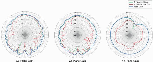
by the gain and radiation pattern. The radiation pattern is a graphical representation of
how the energy radiates off of the antenna in all three dimensions. The gain is a numerical
measurement of the radiated energy, usually in decibels Having
an understanding of gain and radiation pattern will also help you analyze an antenna. The
true measure of the effectiveness of an antenna, no matter its given application, is determined
by the gain and radiation pattern. The radiation pattern is a graphical representation of
how the energy radiates off of the antenna in all three dimensions. The gain is a numerical
measurement of the radiated energy, usually in decibels
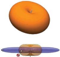
 The
radiation patterns are critical because they show how the antenna radiates energy into the
environment. A perfect antenna puts energy off in a sphere and is called an isotropic radiator.
Real antennas do not have perfect patterns. A normal dipole antenna has a pattern that looks
like a doughnut. It is important for a designer to understand an antenna's radiation pattern
and how it will affect the end product's performance. The
radiation patterns are critical because they show how the antenna radiates energy into the
environment. A perfect antenna puts energy off in a sphere and is called an isotropic radiator.
Real antennas do not have perfect patterns. A normal dipole antenna has a pattern that looks
like a doughnut. It is important for a designer to understand an antenna's radiation pattern
and how it will affect the end product's performance.
Gain can be a somewhat confusing specification. Many engineers think of this term in reference
to amplifiers, where gain is a measure of how much an amplifier increases the input signal.
However, the amplifier puts energy into the system, which makes it an active device. An antenna
is a passive device and cannot put energy into the system. Gain, when related to antennas,
refers to how an antenna focuses the energy that is put into it. A gain of energy in one direction
means that there is less energy in another direction. This has a direct impact on the range
performance of the end device. Application notes
AN-00500 and
AN-00501 go into this in much more detail.
Conclusion
All said and done, when it comes to antenna data sheets, it's important to know that not
all antenna manufacturers specify exactly the same way. This is especially true in the case
of counterpoise size. If you have any questions regarding data sheets, we're here to help
you out.
About Shawn Hogan
 Shawn received
his BS and MS degrees in Physics from the University of Washington in 1991 and 1996. He has
worked at a variety of companies in the sensor and measurement industry in both technical
and management roles prior to joining Linx in 2008. Shawn works as the assistant goat and
chicken wrangler on his family farm when he's not shepherding new products through development. Shawn received
his BS and MS degrees in Physics from the University of Washington in 1991 and 1996. He has
worked at a variety of companies in the sensor and measurement industry in both technical
and management roles prior to joining Linx in 2008. Shawn works as the assistant goat and
chicken wrangler on his family farm when he's not shepherding new products through development.
About Linx Technologies
Linx Technologies makes wireless simple by developing and manufacturing wireless products
that are easy for engineers of all skill levels to use. The company's RF modules, remote
controls, antennas and connectors make it easy for engineers to integrate wireless features
without the hassle and expense of engineering RF functionality from scratch.
For customers who need help implementing Linx modules, Linx offers design services including
board layout assistance, programming, certification advice and packaging design. For more
complex RF solutions, Apex Wireless, a division of Linx Technologies, creates optimized designs
with RF components and firmware selected for the customer's application.
Contact Info 159 Ort Lane Merlin, OR, US 97532 Phone: +1 800
736 6677 +1 541 471
6256 (outside U.S.) Fax: + 1 541 471 6251 www.linxtechnologies.com
Posted October 10, 2013
|


 The information
on an antenna data sheet is nothing short of overwhelming. It can be difficult to maneuver
through to select the best antenna for your design. There are several factors to take into
account when looking at an antenna data sheet including: monopole vs. dipole antennas, the
electrical parameters, counterpoise, gain and radiation pattern. Our goal is to break down
these features so you can use that knowledge to discover advantages and disadvantages of different
antennas as they relate to your specific application.
 A monopole
antenna is one of the elements of the dipole, giving rise to the term quarter-wave monopole.
The other element is usually replaced by a ground plane on the product's circuit board or
a metal enclosure on the device. The ground plane or enclosure is called the antenna's counterpoise.
This reduces the size of the antenna by combining it with something that is in the product
anyway. It also makes the antenna much more dependent on the device's construction. This is
discussed in the counterpoise section.
 The Voltage Standing
Wave Ratio is a measurement of how well an antenna is matched to a source impedance, typically
50-ohms. It's calculated by measuring the voltage wave that is headed toward the load vs.
the voltage wave that is reflected back from the load. VSWR is usually displayed graphically
vs. frequency. The lowest point on the graph is the antenna's operational center frequency.
In most cases, this will be different than the designed center frequency due to fabrication
tolerances. The lower the VSWR, the more energy gets transferred into the antenna and the
better the range of the system. A 1:1 reading is ideal.
 Having
an understanding of gain and radiation pattern will also help you analyze an antenna. The
true measure of the effectiveness of an antenna, no matter its given application, is determined
by the gain and radiation pattern. The radiation pattern is a graphical representation of
how the energy radiates off of the antenna in all three dimensions. The gain is a numerical
measurement of the radiated energy, usually in decibels
 The
radiation patterns are critical because they show how the antenna radiates energy into the
environment. A perfect antenna puts energy off in a sphere and is called an isotropic radiator.
Real antennas do not have perfect patterns. A normal dipole antenna has a pattern that looks
like a doughnut. It is important for a designer to understand an antenna's radiation pattern
and how it will affect the end product's performance.


