|
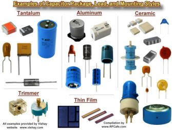  Capacitors are passive devices used in electronic circuits to
store energy in the form of an electric field. They are the compliment of
inductors, which store energy in the
form of a magnetic field. An ideal capacitor is the equivalent of an open circuit
(infinite ohms) for direct currents (DC), and presents an impedance (reactance)
to alternating currents (AC) that depends on the frequency of the current (or voltage).
The reactance (opposition to current flow) of a capacitor is inversely proportional
to the frequency of the of the signal acting on it. Capacitors were originally referred
to as "condensers" for a reason that goes back to the days of the Leyden Jar where
electric charges were thought to accumulate on plates through a condensation process. Capacitors are passive devices used in electronic circuits to
store energy in the form of an electric field. They are the compliment of
inductors, which store energy in the
form of a magnetic field. An ideal capacitor is the equivalent of an open circuit
(infinite ohms) for direct currents (DC), and presents an impedance (reactance)
to alternating currents (AC) that depends on the frequency of the current (or voltage).
The reactance (opposition to current flow) of a capacitor is inversely proportional
to the frequency of the of the signal acting on it. Capacitors were originally referred
to as "condensers" for a reason that goes back to the days of the Leyden Jar where
electric charges were thought to accumulate on plates through a condensation process.
The property of capacitance that opposes a change in voltage is exploited for
the purpose of conducting signals with a higher frequency component while preventing
signals of lower frequency components from passing. A common application of a capacitor
in an RF (radio frequency) circuit is where there is a DC bias voltage that needs
to be blocked from being present in a circuit while allowing the RF signal to pass.
DC power supplies use large capacitance values in parallel with the output terminals
to smooth out low frequency ripples due to rectification and/or switching waveforms.
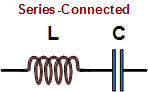 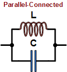 When used
in series (left drawing) or
parallel (right drawing) with its circuit
compliment, an inductor, the inductor-capacitor combination forms a circuit that
resonates at a particular frequency that depends on the values of each component.
In the series circuit, the impedance to current flow at the resonant frequency is
zero with ideal components. In the parallel circuit (right), impedance to current
flow is infinite with ideal components.
Real-world capacitors made of physical components exhibit more than just a pure
capacitance when
 present in an AC circuit. A common circuit
simulator model is shown to the left. It includes the actual ideal capacitor with
a parallel resistive component ('Leakage') that responds
to alternating current. The equivalent DC resistive component
('ESR') is in series with the ideal capacitor and
an equivalent series inductive component ('ESL') is
present due to metal leads (if present) and characteristics of the plate surfaces.
This inductance, in combination with the capacitance, creates a resonant frequency
at which point the capacitor looks like a pure resistance. present in an AC circuit. A common circuit
simulator model is shown to the left. It includes the actual ideal capacitor with
a parallel resistive component ('Leakage') that responds
to alternating current. The equivalent DC resistive component
('ESR') is in series with the ideal capacitor and
an equivalent series inductive component ('ESL') is
present due to metal leads (if present) and characteristics of the plate surfaces.
This inductance, in combination with the capacitance, creates a resonant frequency
at which point the capacitor looks like a pure resistance.
As the operational frequency is increased past resonance
(aka self-resonant frequency, or SRF), the circuit
behaves as an inductance rather than a capacitance. Hence, careful consideration
of the SRF is required when selecting capacitors. SPICE-type simulators use this
or an even more sophisticated model to facilitate more accurate calculations over
a wide range of frequencies.
Equations for combining capacitors in series and parallel are given below. Additional
equations are given for capacitors of various configurations. As these figures and
formulas indicate, capacitance is a measure of the ability of two surfaces to store
an electric charge. Separated and isolated by a dielectric (insulator), a net positive
charge is accumulated on one surface and a net negative charge is stored on the
other surface. In an ideal capacitor, charge would be stored indefinitely; however,
real world capacitors gradually lose their charge due to leakage currents through
the non-ideal dielectric. These calculations are included in the free
Espresso Engineering Workbook.


Total capacitance of series-connected capacitors is equal to the reciprocal of
the sum of the reciprocals of the individual capacitances. Keep units constant.
|
|


Capacitance (C, in Farads) of two equal-area parallel plates is the product of
the area (A, in meters) of one plate, the distance (d, in meters) separating the
plates, and the dielectric constant (ε, in Farads per meter) of the space
separating the plates. ε, the total dielectric constant, is the product
of the dielectric constant of free space, ε0, and the relative
dielectric constant of the material, εr. Note that units of length
and area can be metric or English so long as they are consistent.
|
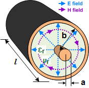
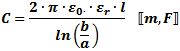
Length (l)
in meters
|
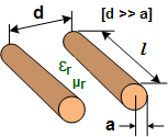

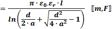
Length (l) in meters
|


|
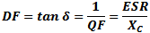
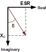 Dissipation
Factor (DF), aka Loss Tangent (tan δ) is interchangeably defined as the reciprocal
of the Quality Factor (QF) or the ratio of the equivalent series resistance (ESR)
and the capacitive reactance (XC). It is a measure of the loss rate of
stored charge. DF is typically used in low frequency applications while tan δ is
more often used in high frequency applications. Dissipation
Factor (DF), aka Loss Tangent (tan δ) is interchangeably defined as the reciprocal
of the Quality Factor (QF) or the ratio of the equivalent series resistance (ESR)
and the capacitive reactance (XC). It is a measure of the loss rate of
stored charge. DF is typically used in low frequency applications while tan δ is
more often used in high frequency applications.
|
|


Total capacitance of parallel-connected capacitors is equal to the sum of the
individual capacitances. Keep units constant.
|
|
The following physical constants and mechanical dimensional variables apply to
equations on this page. Units for equations are shown inside brackets at the end
of equations; e.g.,  means lengths
are in inches and inductance is in Henries. If no units are indicated, then any
may be used so long as they are consistent across all entities; i.e., all meters,
all µF, etc. means lengths
are in inches and inductance is in Henries. If no units are indicated, then any
may be used so long as they are consistent across all entities; i.e., all meters,
all µF, etc.
C = Capacitance
L = Inductance
W = Energy
εr = Relative permittivity (dimensionless)
ε0 = 8.85 x 10⁻¹² F/m (permittivity
of free space)
µr = Relative permeability (dimensionless)
µ0 = 4π
x 10-7 H/m (permeability of free space)
1 meter = 3.2808 feet <—> 1 foot
= 0.3048
meters
1 mm = 0.03937 inches <—> 1 inch
= 25.4 mm
Also, dots (not to be confused with decimal points)
are used to indicate multiplication in order to avoid ambiguity.
|
 Capacitive reactance (XC, in Ω)
is inversely proportional to the frequency (ω, in radians/sec, or f, in Hz)
and capacitance (C, in Farads). Pure capacitance has a phase angle of -90° (voltage
lags current with a phase angle of 90°).
|
 Charge (Q, in coulombs) on a capacitor's plates
is the product of the capacitance (C, in Farads) and the voltage (V, in volts) across
the device.
|
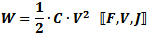 Energy (W, in Joules) stored in a capacitor
is half the product of the capacitance (C, in Farads) and the voltage (V, in volts)
across the device.
|
 Current does actually flow 'through' an ideal
capacitor. Rather, charge stored on its plates is given up to the connected circuit,
thereby facilitating current flow. Conversely, a net voltage applied to its plates
causes a current to flow in the connected circuit as charge accumulates on the plates.
|
 Quality factor is the dimensionless ratio of
reactance to resistance in a capacitor.
|
|
Related Pages on RF Cafe - Capacitors &
Capacitance Calculations -
Capacitor
Color Codes - Capacitance Conversions -
Capacitor Dielectrics -
Standard Capacitor Values -
Capacitor Vendors -
The Noble Art of De-Coupling
|