|
Unless otherwise annotated, U.S. Government publications are deemed to be in
the public domain for American citizens. Since government websites are famous for
moving pages around and/or eliminating them entirely, I went ahead and captured
this copy of the wire-wrapping workmanship standards as defined by NASA. In fact,
many moons ago when working as an electronics technician at the Westinghouse Oceanic
Division in Annapolis, Maryland, I attended a week-long class learning to perform
soldering, wire-wrapping, and PCB rework per NASA standards. My work involved a
lot of building electronic and mechanical assemblies for DoD and aerospace systems,
and U.S. Navy inspectors were on-site to perform inspections on everything I built.
I created this page while researching information for this "Bell Telephone Laboratories
Advertisement" that appeared in the October 1953 issue of Radio & Television
News magazine.
Original Source Page:
Discrete Wiring Solderless Wrapped Electrical Connections - Wire-Wrap
You are advised to seek official documentation for work requiring conformance rather
than using information on this page.
 |
Released: 03.31.2000 |
Revision: A |
Revision Date: 03.30.2001 |
| Book: 3 |
Section: 3.01 |
Pages: 1-4 |
 |
Wire Wrapping
Solderless wrapped terminations are made by helically wrapping a solid uninsulated
wire, around a specially designed termination post, to produce a mechanically and
electrically stable connection.
Class A: Class A provides improved vibration characteristics, and
is the required wrap style for spaceflight hardware applications. This wrap configuration,
requires 1/2 to 1-1/2 turns of insulated wire be in contact with a minimum of three
(3) corners of the wrappost, in addition to the uninsulated wraps.
Class B: Class B wraps are prohibited.
|
 |
 |
|
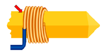
Acceptable
Class A – Single Termination
The termination has the required number of insulated and uninsulated turns of
wire, and is clean and free of foreign material.
MIL-STD-1130B [ 4.1 ]
|
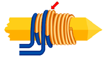
Acceptable
Class A – Multiple Terminations
The terminations are properly spaced, with each having the required number of
insulated and uninsulated turns of wire, and are clean and free of foreign material.
MIL-STD-1130B [ 4.1 ]
|
 |
 |
|
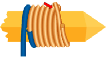
Acceptable
Overlapped Turns
The insulated conductor overwrap does not exceed one (1) turn, and the termination
wrap is tight.
MIL-STD-1130B [ 5.3.2.1 b ]
|
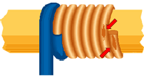
UNAcceptable
Class B
Class B terminations, characterized by the absence of insulated turns, are prohibited.
Best Workmanship Practice
|
 |
 |
|
UNAcceptable
Insufficient Insulation Wrap
The insulated section of the termination must be in contact with a minimum of
three (3) corners of the wrappost.
MIL-STD-1130B [ 5.3.2.1 a ]
|
UNAcceptable
Overlapping Wraps
The overlapping wrap must not exceed one (1) complete turn over the last turn
of uninsulated wire in a termination directly below it on the wrappost.
MIL-STD-1130B [ 5.3.2.1 b ]
|
 |
 |
|
UNAcceptable
Improper Position - Single Wrap
The first wrap should be located as low on the post as practical, providing sufficient
space for additional terminations later.
MIL-STD-1130B [ 5.3.2.1 b ]
|
UNAcceptable
Improper Position - Multiple Wraps
Terminations in a multiple wrap configuration must be properly positioned to
ensure the wraps are completed within the defined termination area of the wrappost.
MIL-STD-1130B [ 5.3.2.1 b ]
|
 |
 |
|
UNAcceptable
Insufficient Turns
The uninsulated section of the termination shall have the minimum number of complete
turns, as specified by MIL-STD-1130B, or as noted on the engineering documentation.
MIL-STD-1130B [ 5.3.2 ]
|
UNAcceptable
End Tail
An end tail is the end of the last turn of wire that is protruding in a tangential
direction from the surface of the wrappost. End tails present a risk of shorting.
MIL-STD-1130b [5.3.2.1.d]
|
 |
 |
|
UNAcceptable
Overwarp
Overlapping wraps reduce the reliability of the termination and may result in
severed wraps.
MIL-STD-1130B [ 5.3.2.1 j ]
|
UNAcceptable
Spiral Wrap
The space between adjacent wrap turns shall not exceed one-half uninsualted conductor
diameter. The sum of all gaps shall not exceed one wire diameter, excluding the
first and last turn.
MIL-STD-1130B [ 5.3.2.1 f ]
|
 |
 |
|
UNAcceptable
Open Wrap
An open wrap is an indicator of an improper termination process and may reduce
the reliability of the termination.
MIL-STD-1130B [ 5.3.2.1 f ]
|
UNAcceptable
Improper Routing
The wire shall not be routed in any manner that will tend to unwrap the termination,
and shall be routed around and between the wrapposts in a manner that prevents shorting
to adjacent wrapposts.
MIL-STD-1130B [ 5.3.2.1 g ]
|
 |
 |
|
UNAcceptable
Damaged Wrappost
The wrappost shall not exhibit evidence of cracking, flaking plating, bending,
excessive twisting, gouging or exposed base metal.
MIL-STD-1130B [ 5.3.2.1 a ]
|
UNAcceptable
Damaged Wrappost
The wrappost shall not exhibit evidence of cracking, flaking plating, bending,
excessive twisting, gouging or exposed base metal after wire wrapping.
Best Workmanship Practices
|
 |
 |
|
UNAcceptable
Damaged Conductor
After removal of the insulation, the conductor shall not exhibit nicks, cuts,
exposed base metal, ringing or reduction of cross-sectional area. Burnishing of
the wire surface is Acceptable.
MIL-STD-1130B [ 5.3.2]
|
UNAcceptable
Damaged Conductor
After wrapping, the conductor shall not exhibit nicks, cuts, exposed base metal,
ringing or reduction of cross-sectional area. Burnishing of the wire surface is
Acceptable.
Best Workmanship Practice
|
 |
 |
|
UNAcceptable
Damaged Insulation
Cut, crushed, gouged, damaged or nicked insulation may result in reduced electrical
isolation and/or short circuits. Slight scuffing or discoloration is Acceptable.
Best Workmanship Practice
|
UNAcceptable
Contamination
Contamination reduces the reliability of the termination.
Best Workmanship Practice
|
 |
 |
|
UNAcceptable
Stranded Conductor
The use of standard conductor for wire wrapping is prohibited.
Best Workmanship Practice
|
UNAcceptable
Silver Underplating
The use of wrapposts with silver underplating is prohibited. Gold plating over
nickel is preferred.
MIL-STD-1130B [5.3.2.1 a]
|
Disclaimer on NASA Website:
All diagrams and visual aids included in this section are intended to provide
insight to certified operators, inspectors and instructors who visually assess the
compliance of flight hardware to locally applicable requirements. The statements
found in this pictorial reference are not intended to be applied as requirements
and this pictorial reference should not be applied to contracts. Your project or
contract requirements should take precedence over the pictures and statements in
this pictorial reference if there is a conflict. Refer to your local project or
contract documents for applicable workmanship requirements.
See NASA Workmanship
Standards Program Website.
|


