|
|||||||||||||
 |
|||||||||||||
Basic Digital Logic Course - Part 2
|
|||||||||||||
English mathematician George Boole published his "Formal Logic" syllogism system of deductive reasoning in 1847. Fellow countryman Augustus De Morgan followed on Boole's work to develop the basic combinational logic rules the AND gates, OR gates, and NOT (negation) operators. What has become known as Boolean algebra and De Morgan's theorem forms the fundamental foundation of everything related to digital logic. This second in a three-part series from a 1974 issue of Popular Electronics introduces both concepts at a beginner's level. Part 3 will present flip-flops and an overview of how all the parts come together to build a simple computer. See Part 1, Part 2, and Part 3. Basic Digital Logic Course - Part 2: Concepts and Circuits
In part 1 of our short course in digital logic, we discussed the binary number system, binary arithmetic, and the octal number system. In Part 2, we are concerned with logic concepts and circuits. Boolean Logic In 1847, George Boole, a British mathematician, published his Mathematical Analysis of Logic. This booklet did not equate mathematics with logic, but it did demonstrate how any logic statement can be analyzed with basic mathematical relationships. Boole published a much longer and refined version of his theory of logic in 1854. To this day, all practical digital computers and countless other electronic digital circuits are based on the concepts pioneered by Boole. Boolean logic (or algebra) makes the important assumption that a logic statement is either true or false. Since electronic circuits can easily be made to operate in either of two states, on or off, it is convenient to equate "true" with "on" and "false" with "off." Similarly, we can equate the binary 1 with on and the binary 0 with off. With the foregoing in mind, let us review Boole's basic logic concepts.
Fig. 1 - Switches are arranged to illustrate three basic digital electronic functions. The mathematical explanation of logic put forth by Boole can be simplified into three basic logic functions: AND, OR, and NOT. The AND function requires that one logic state or condition and at least one other be true before the entire statement is true. The OR function requires that one logic state or at least one other be true before the entire statement is true. The NOT function simply reverses a statement from true to false, or vice versa. Electronic NOT circuits are commonly referred to as "inverters" because their function is to invert the polarity of the signal. The above definitions can be tabulated into a table such as shown in Fig. 1. Such a table is useful in showing the relationships among Boole's three logic functions and their electronic and arithmetic counterparts. This type of table is sometimes called a "truth table" since it sets forth the various logic conditions for which each statement is true. Generally, truth tables are arranged in a more compact form similar to those shown for the three basic logic functions in Fig. 2. Truth tables can be created for any logic function. Specification sheets for digital logic circuits almost always include a truth table. Logic Symbols. Boolean logic statements can be implemented by simply writing them on paper, using alphabetic symbols to correspond to "true" and "false" conditions. Electronic logic diagrams, however, are much easier to design and interpret if a sort of block diagram of the circuit is presented. For this reason, standardized logic-block symbols have been devised for the three basic logic functions. They are shown in Fig. 2. Compound Logic Circuits Two circuit combinations (the NOT-AND and the NOT-OR) are used so frequently that they are treated as basic logic elements and given their own logic symbols and truth tables.
Fig. 2 - AND, OR, and NOT symbols are shown with truth tables.
Fig. 3 - NAND and NOR symbols with associated truth tables. When the AND function is followed by a NOT statement, the meaning of the AND function is reversed to NOT-AND, commonly called a NAND function. Similarly, when the OR function is followed by a NOT statement, the meaning of the OR statement is reversed to NOT-OR, commonly referred to as a NOR function. The logic symbols and truth tables for the NAND and NOR functions are shown in Fig. 3. DeMorgan's Theorem About the same time Boole developed his logic theories, Augustus DeMorgan was also developing some fundamental theories of logic. His most important contribution, known as DeMorgan's Theorem, relates the AND, OR, and NOT functions as follows: A + B= A x B. A x B = A + B. The arithmetic symbols + and x mean OR and AND, respectively. The bar, or vinculum, over a letter indicates the NOT function. Thus A means NOT A. The importance of DeMorgan's Theorem is that an AND circuit containing a NOT at each input corresponds to an OR circuit followed by a NOT. Similarly, an OR circuit with a NOT at each input corresponds to an AND circuit followed by a NOT. This does not equate the NAND and NOR functions, but it does mean that NAND circuits can be used to implement NOR functions, and vice versa. Complex Logic Systems Logic systems that contain three or more basic logic elements are termed "complex." One of the simplest of the complex logic systems is the EXCLUSIVE OR (sometimes written XOR) function shown diagrammatically in Fig. 4. From the truth table, note that this function is identical to the OR function with one important exception: A true condition exists only when one or the other condition, but not both, is true. The EXCLUSIVE OR function completes the connection between Boolean logic, the binary number system, and electronic switching circuits, for it can be used to add two binary bits. To see how this is accomplished, assume a logic 1 at input A and a logic 0 at input B in the EXCLUSIVE OR circuit shown in Fig. 4. Since only one input is enabled (input A), AND circuit 1 does not turn on. Hence, a 0 is present at the CARRY output. OR circuit 1 does turn on, since only one input need be present. Since the NOT circuit inverts the 0 from AND circuit 1 into a logic 1, AND circuit 1 has two input signals and is therefore turned on. The result is a logic 1 at the sum output. (The circuit has added 0 + 1 to obtain 1.)
Fig. 4 - Logic array for XOR circuit. The EXCLUSIVE OR circuit is often called a "half-adder." Try verifying its operation yourself by adding 1 + 1 in binary. Practical Logic Circuits. Figure 1 demonstrated how simple switching circuits can be used to implement each basic logic function. However, it is usually not practical to employ switches in real systems. Instead, transistors, SCR's, tunnel diodes, or other solid-state switches are employed. The most commonly used switch in digital electronics is the transistor. Relatively simple circuits that combine diodes, resistors, and transistors can be used to implement the AND, OR, and NOT functions. Thanks to integrated circuit (IC) technology, several or even dozens of individual logic circuits can be placed on a single compact silicon chip. Resistor-transistor logic (RTL) was once the most popular type of digital IC, but it has been largely replaced by the more noise-immune transistor-transistor logic (TTL) type. In recent years, field-effect transistor (FET) technology has been adapted to integrated logic circuits of amazing complexity. By insulating the gate of a FET with a layer of silicon dioxide, extremely high impedances are made possible. The result is a logic circuit that requires microamperes or nanoamperes of operating current at relatively low voltages. Insulated-gate fabrication techniques are collectively known as MOS (for metal oxide semiconductor) technology. Since MOS transistors are unipolar (p- or n-type) and do not require separate p and n sections like conventional bipolar pnp and npn transistors, MOS IC's can have a much higher component density than most conventional IC's. The result is large-scale integration (LSI). So, the next time you read or hear the phrase "MOS LSI," you will know that it refers to a large scale integrated circuit employing metal oxide semiconductors. |
|||||||||||||
 |
|||||||||||||
|
|||||||||||||

 By Forrest M. Mims and H. Edward Roberts
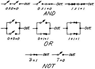


|
||||||||||||||||||||||||||||||||||||


