|
|||||||||||||
 |
|||||||||||||
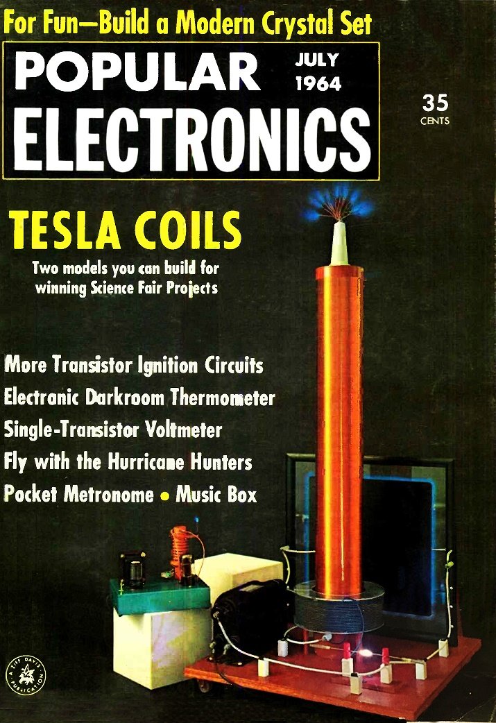
Big Tesla Coil
|
|||||||||||||
This 1964 Popular Electronics magazine article describes building "Big TC," a Tesla coil inspired by Nikola Tesla, capable of producing nearly 250,000 volts. It creates spectacular foot-long corona discharges and excites neon or fluorescent lamps up to five feet away. Costing about $30 (in 1964), it's ideal for demonstrations or science fairs. The circuit features a 12,000-volt neon sign transformer charging a glass-plate capacitor, which discharges through a spark gap into primary coil L1 (20 turns of heavy wire). This generates radiofrequency harmonics, stepped up by secondary coil L2 (2,000 turns of No. 26 wire). Assembled on a 22" x 22" plywood base, components use high-voltage wire, insulators, and standoffs. The spark gap employs brass/copper rods; the capacitor uses tin plates on glass. Output voltage increases with additional parallel capacitors (up to 200,000-300,000 volts), tested via arcing. Current is microamps, but extreme caution is urged. An accompanying article describes the "Small TC." See Tesla's Trickery, A Tesla Coil, Big Tesla Coil. Big Tesla Coil
A quarter of a million volts? All It takes is a transformer, a capacitor, a spark gap, and Tesla's famous coil.
By Charles Caringella, W6NJV
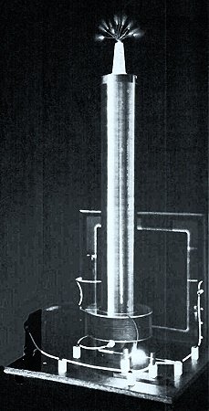
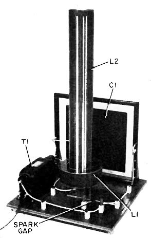
Mount L1-L2 in center of base, T1 and C1 at edges. A bigger base and greater component spacing will permit greater voltage output with less arcing. WARNING: The voltages used. in this project are highly dangerous. Inexperienced persons should seek aid from an instructor or other expert before building it. Tesla coils have fascinated experimenters ever since the early 1900's when Nikola Tesla first experimented with giant coils that produced lightning-like discharges which would span his laboratory - the work of millions of volts of electricity. The Tesla coil described here is smaller than some of Tesla's designs, but it's capable of putting out almost a quarter of a million volts! Brilliant corona discharges as long as a foot or more provide a spectacular display of its intense electrical field, and neon and fluorescent lamps can be excited as far as five feet away. Intended both as a dynamic demonstrator of electrical principles and as a crowd-attracting science fair project, "Big TC" can be put together for about $30. However, if a used transformer from o neon sign shop can be se- cured reasonably, the cast will be even less. As shown in the schematic diagram above, T1 steps the household line voltage up to 12,000 volts. The transformer is the type commonly used to operate neon signs. A high -voltage glass-plate capacitor, C1, is connected directly across the high-voltage secondary winding of T1. The capacitor serves as an energy storage device, charging up to T1's secondary voltage and then discharging in response to the 60-cycle a.c. voltage. Discharging of C1 is through the spark gap into coil L1. Each time the spark gap "fires," a high current flows through L1. The larger capacitor C1 is made, the larger will be the current through L1. Discharges across the spark gap produce extremely jagged pulses of power which are very rich in r.f. harmonics. The energy - due to the values of the components used - is greatest in roughly the 100-kc. region. Windings L1 and L2 form an air-core step-up transformer, with L1 the primary and L2 the high-voltage secondary. The voltage at L2 will be 75,000 to 250,000 volts depending on the size of Cl. Design and Layout. The prototype of "Big TC" was built on a plywood base measuring 3/4" x 22" x 22", although a larger base would be desirable for high-voltage units to prevent arcing between L2 and T1 and C1. Mount L2 in the center of the base and T1 and C1 as close to the edges as possible; if you plan to operate the unit at voltages exceeding 100,000 volts, make the base 3' x 3' for even greater separation between components. Power transformer T1 is the only high -cost component. A neon-sign unit rated at 12,000 volts a.c. at 30 ma., it sells for about $40 new, but used transformers are constantly being salvaged by sign shops, and can be picked up for $10 to $20. It is also possible to find neon signs in junk yards, in which case you can probably buy the transformer for practically nothing. The author used a GE unit, No. 51G473, known technically as a "luminous tube transformer." Measuring 91/2" x 6" x 4", it has 2" feedthrough insulators at either end connecting to the high -voltage winding. Primary coil L2 and all connecting leads must be made with high -voltage wire, preferably supported away from the base on 1" ceramic standoff insulators. Test prod wire such as Belden Type 8898 is ideal-it has flexible rubber insulation with a puncture voltage rating of 29,000 volts.
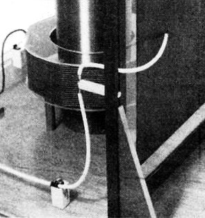
Spark gap generates r.f. energy to excite coil. It consists of two copper rods mounted on standoffs.
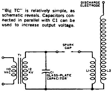
"Big TC" is relatively simple, as schematic reveals. Capacitors connected in parallel with C1 can be used to increase output voltage.
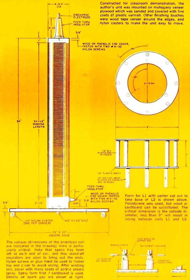
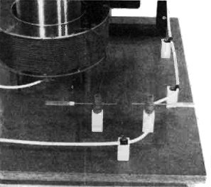
Leads are soldered directly to capacitor plates. Note use of stand-off insulators. Winding the Coil For the big coil (L2) a phenolic coil form measuring 43/4" in outside diameter and 38" in length was used. Alternately, cardboard, wood or other insulating materials can be substituted. You can improve these latter types of coil forms by spraying on at least six coats of acrylic plastic spray before winding the wire on them. The winding itself is done with No. 26 Formvar-insulated wire-two 1 -lb. spools (splice them together and keep the solder joint as small as possible) will give you a 2000-turn, tightly spaced coil covering 34 1/2" of the coil form. There should be extra space between the ends of the winding and the ends of the form - see the drawing on page 31. The lower end of the coil is terminated at a 1" feedthrough insulator installed in the side of the form, the top end of the coil at a 4 1/2" feedthrough mounted to the top end of the form. Make the end covers of wood or phenolic discs cut to the inside diameter of the coil form, and mount them in place with nylon screws (metal screws at the top end would produce corona discharges which could burn the coil form). Alternatively, the top coil cover can be cemented in place with epoxy cement if a sturdy coil form is used. The coil is attached to the base with a 3/8" bolt. Winding the coil is not nearly as difficult as it appears-the author completed the task in about two hours. Spray the entire winding with acrylic plastic for added insulation, moisture protection, and to keep the windings in place. You can't overdo this step - the author used the contents of an entire aerosol spray can on the prototype, applying one thin layer at a time and letting it dry before adding another. Building the Primary. As shown on page 31, the form for LI was made with polystyrene rods and sheeting. While the plastic has excellent insulating qualities and looks attractive, wood or even cardboard can be substituted. If plastic is used, it can be strongly "welded" together with acetone. Regardless of the material used, the form should have an outside diameter of at least 9" to avoid arc -over between Ll and L2. The coil itself (L1) consists of 20 turns of heavy test prod wire.
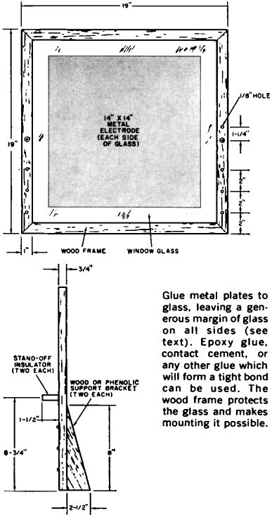
Glue metal plates to glass, leaving a generous margin of glass on all sides (see text). Epoxy glue, contact cement, or any other glue which will form a tight bond can be used. The wood frame protects the glass and makes mounting it possible. Spark Gap The spark gap is simply two ordinary binding posts mounted on stand-off insulators. In turn, these are mounted on a phenolic base measuring 3/8" x 2 1/4" x 6". The electrodes are brass and copper rods with a gap on the order of 1" between them. This distance will vary slightly, depending on the size of capacitor C1. Fabricating the Capacitor. The capacitor consists of two 14" x 14" sheets of tin cemented to a 18 1/2" -square piece of window glass. Although aluminum foil can be used for the capacitor plates, tin was obtained from a sheet metal shop for this purpose so that connecting leads could be soldered directly to it. If you use aluminum foil, a fairly good connection can be had by making leads of IA" - wide aluminum foil strips and taping them down to the electrodes. Glass is an excellent dielectric material for this application since it has an extremely high puncture voltage and a high dielectric constant. As you will note in the drawing on page 32, a border of glass is left around the capacitor plates-this should be at least 1 1/2" wide. The calculated capacity of C1 is approximately 0.0027 I.if. Testing and Operation. Caution! Adjustments to the Tesla coil, and specifically to the spark gap, should be made only when the unit is off. Although the output voltage of the Tesla coil may be on the order of 150,000 volts, the current capacity is only hundreds of microamps. This current can inflict a nasty shock and r.f. burns, however. Use EXTREME CAUTION around the neon sign transformer. It delivers 12,000 volts at 30 ma., and this voltage could be lethal under certain conditions. Again, be sure the plug is out when you make adjustments. To adjust the spark gap, first open it to about 11/9"; it will not fire at this point. Gradually move the electrodes together-unplugging the unit each time you adjust the gap-until the point is reached where the gap "fires." The author's version of "Big TC" produced an output voltage of 100,000 volts with the 0.0027-µf. capacitor described. To increase the output voltage, simply construct one or two more capacitors and parallel them across Cl. With two capacitors in parallel, the prototype Tesla coil produced 150,000 volts; with three capacitors, 200,000 volts. However, it began to break down between coil L2 and capacitor C1 above the 200,000 -volt region. As mentioned earlier, greater output voltage can be obtained by making the base larger and increasing the spacing between components to eliminate arcing. The output of your Tesla coil can be estimated by drawing an arc to a metallic object attached to a long wooden handle. Slowly increase the distance between the object and the discharge terminal until the arcing stops: a 6" arc represents 100,000 volts, a 14" arc about 200,000 volts, and a 21" arc some 300,000 volts. More amazing than figures, however, are the brilliant, spectacular phenomena exhibited by high - voltage, high -frequency electricity.
* Tubing can be found in metropolitan areas at surplus houses and establishments which sell plastics (sheets, rods, etc.). Clear acrylic tubing (48" long, 41" O.D.) can be ordered from Industrial Plastics Supply Co.. 324 Canal St., New York, N. Y. 10013. for $13.85 including shipping charges and postage: address sour order to the attention of Mr. Charles Roth. Constructed for classroom demonstration, the author's unit was mounted on mahogany veneer plywood which was sanded and covered with five coats of plastic varnish. Other finishing touches were wood tape veneer around the edges, and nylon casters to make the unit easy to move. The various dimensions of the prototype coil are Indicated in the drawing; none is particularly critical. Note that space has been left at each end of coil, and that stand-off insulators are used to bring out the ends. Nylon Screws or glue mast be used to fasten top end cover to avoid arcing. After winding coil. cover with many coats of acrylic plastic spray. Spray form first f cardboard is used. Details on spark gap are shown at right. Form for L1 with center cut out to take base o= L2 is shown above. Polystyrene was used, but wood or cardboard can be substituted. The critical dimension is the outside diameter; less than 9" will result in arcing between coils L1 and L2. |
|||||||||||||
 |
|||||||||||||
|
|||||||||||||

|
||||||||||||||||||||||||||||||||||||


