|
|||||||||||||
 |
|||||||||||||
One Receiver, All Bands
|
|||||||||||||
One Receiver, All Bands... thanks to plug-in coils
Receiving Tube Dept., General Electric Co., Owensboro, Ky. Most of today's short-wave receivers are truly sensitive and reliable devices, but they are also rather complex and expensive for the beginner to construct. Here's a simple receiver, using one compactron tube, that will give you long-wave, broadcast-band, and short-wave reception. If you are considering putting your first receiver together, this one is for you. If you, have an amateur-band-only receiver, this unit will fill in some of the "holes" in the spectrum. Finally, if you already have a general-coverage receiver, this set will make a good "auxiliary" to tuck a way on a corner of the desk just in, case your "big" one quits. Use of a compactron allows a lot of receiver to be contained in a small box without undue crowding. the frequency range covered is from 250 kc. all the way to 16 mc.; and, since plug-in coils are used, it's possible to extend the range in either direction. Plenty of headphone volume is provided, and many signals will operate the built-in speaker in a very satisfactory manner. The Circuit
Single-tube multi-band receiver schematic.
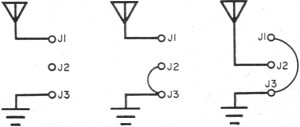
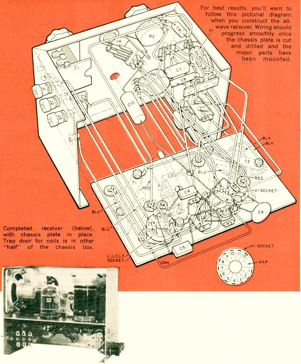
Versatility is the word on antenna hookups for this receiver, and three possible configurations are shown. The 6AF11 compactron contains two triodes and a pentode. One triode is used a regenerative detector, the other as an audio voltage amplifier, and the pentode as an audio power amplifier. Plug-in coils containing primary (L1), secondary (L2), and tickler (L3) windings determine the frequency range. Tuning is done with a relatively large variable capacitor (C2) to allow covering a wide range of frequencies with a minimum of coils. For fine tuning, a small variable capacitor (C3) is connected in parallel with the larger one to act as a "vernier." The antenna coupling circuit is purposely designed for versatility. Straight inductive coupling, series tuning, or parallel tuning are possible, depending on the connections to jacks J1, J2, and J3 (see antenna hookup diagram). This can be quite helpful in increasing the selectivity of the receiver and in tuning out the "dead spots" that afflict most regenerative receivers. For maximum audio output, the headphones are operated from the pentode section of the compactron, and the phone jack (J4) is arranged to disconnect the speaker when the phones are in use. The Receiver All parts of the receiver, with the exception of the spare-coil rack, and the trap door for coil changing, are mounted on the portion of the chassis box used to form the front panel and sides. As the photos show, this makes all parts of the receiver readily accessible to the builder. In addition, since no electrical components are mounted on the removable portion of the box, all the testing that is necessary can be done before the cabinet is "buttoned up." To reduce sheet metal bending to a minimum, the chassis proper is a fiat plate, cut to make a fairly snug fit, and then fastened in place with four small angle brackets. All mounting holes should be cut in this plate and the chassis box before the plate is bolted in place. After the holes have been drilled, all of the parts should be mounted, since they are all readily accessible for wiring in any sequence. In mounting the 40 p.p.f. antenna tuning capacitor (C1), flat washers should be used between the panel and the capacitor frame to insure that the screws don't extend through the frame far enough to interfere with the rotor. Wiring of the receiver isn't especially critical, and the receiver is compact enough to allow component leads to fur-nish many of the connections. However, be careful to wire the coil socket exactly as shown, since proper wiring here is just as important as on the tube socket.
Chassis Assembly Wiring Drawing The Power Supply. A separate entity, the power supply is built on a 5" x 2¼" x 2¼" chassis box. Holes for the various parts should be drilled in the box and all parts mounted before any wiring is done. Again, the wiring isn't critical, although care should be taken in connecting leads to the output socket (J5) to make sure that the proper socket con-tacts are used. 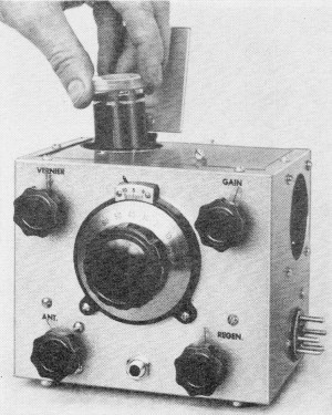 No likelihood of losing coils with this set - one inserted through a trap door is always in use.
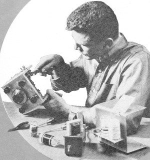
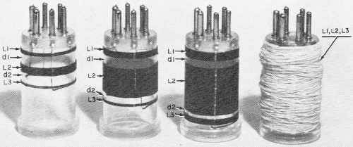
The other three rest in empty sockets mounted on aluminum flange at rear of cabinet. The Coils. Before the receiver can be tested, at least one of the plug-in coils must be wound. Start with the broadcast coil, since it covers the range where results are easiest to obtain. The polystyrene forms will call for some cautious handling-when drilling, too much pressure may crack them; and, when soldering, excessive heat will soften them. Lightly filing the ends of the coil form pins to remove the plating will make soldering easier. Remember, rapid soldering is required to prevent soften-ing of the form. Start by winding the primary, followed by the secondary, and then the tickler. One way to make a neat job is to push the wire through the starting hole in the form and into the pin and then solder it in place. Then unwind the amount of wire from the spool that you think will be required, but don't cut the wire just yet. Instead, clamp the spool in a vise and walk away until the wire is under slight tension. Wind the coil by turning the coil form in your hands as you walk slowly toward the vise. If you have underestimated the wire needed, or if your workshop is small, hold the coil in one hand to prevent the wire from slipping, remove the spool from the vise, unwind more wire, re-clamp the spool, and continue winding. If you take your time, you should have a professional-looking winding job with the wire tightly wound and uniformly spaced. When the proper number of turns has been wound on, cut off the wire (leaving a lead of about 6/1) , put the wire through the proper hole in the form, place your thumb over the hole to hold the wire in place, remove the insulation from the wire, push the wire through the proper base pin, and solder it in place. Incidentally, it's especially important that the secondary and tickler coils (L2 and L3, respectively) be wound in the same direction. If they're not, the re-generative detector won't operate properly. In the event that you experience trouble in getting the set to oscillate, try reversing connections to either L2 or L3 - not both! Although information on the other coils is given below, it will probably be better for you to skip over to the "Operation" section at right, read that material, and try the receiver. Then you can come back and wind the other coils. Three of the coils are single-layer af-fairs, and are all wound in the same manner (one being the broadcast-band coil described above). However, it's im-possible to place enough wire in a single layer on the 250 - 600 kc. coil, so a different winding style is used for this one. To wind the 250 - 600 kc. coil, drill all of the holes in the form, but wind the secondary coil (L2) first. Solder one end of the wire in place and make several large looping turns up to the hole at which the secondary coil will end. Now start back down the coil and wind in the same manner, reaching the hole in the form where the coil started in only a few turns. Continue winding up and down the form until the specified number of turns are in place. The purpose of this winding method is to make as many of the turns as possible cross at angles rather than lie parallel and thus reduce the distributed capacitance. After the secondary has been completed, wind the primary (L1) and tickler (L3) coils at the proper ends of the form. These coils should be scrambled-wound, with the turns touching the ends of the secondary. Strips of plastic cement or coil dope can be run vertically at ½" intervals around the forms to hold the wires in place.
Various Wound Coils Operation. Check the wiring, connect the power supply to the receiver with the power supply cable, and plug in the broadcast coil. Connect an antenna to the ANT 1 binding post (J1), and a ground to the GND binding post (J3). Set the REGEN control (R2) in the extreme counterclockwise position, the ANT (C1) and GAIN (R6) controls in the extreme clockwise position, and the VERNIER control (C3) in the center of its range. Turn on the power supply. After warm-up, turn the REGEN control clockwise until a hissing sound is heard in the speaker. Now back off the control until the hiss just stops; this is the most sensitive point for reception of AM stations. If you have trouble separating strong local stations, turn the ANT control counterclockwise. This increases the selectivity by decreasing the coupling of the antenna to the receiver. With extremely strong local stations, it may be necessary to use a very short antenna to limit the signal strength. When you use the short-wave coils, you'll find that adjusting the tuning and regeneration controls is more critical. Tuning is best done by adjusting the main dial to the vicinity of the station you wish to hear and then doing the fine tuning with the VERNIER capacitor. Set the regeneration control to the point where the hiss starts to receive c.w. signals; and just below this point to receive phone signals. If the receiver refuses to oscillate at certain dial settings, change the antenna coupling by means of the ANT capacitor, or try the alternative antenna connections shown in the diagram on page 40. With the long-wave coil in place, the receiver should handle about as it does on the broadcast band. And don't forget that additional coils to extend the range in both directions can be wound in a cut-and-try fashion.
One Receiver - All Wave Parts List
Posted October 19, 2022 |
|||||||||||||
 |
|||||||||||||
|
|||||||||||||

 By Philip E. Hatfield, W9GFS


|
||||||||||||||||||||||||||||||||||||


