|
February 1953 QST
 Table
of Contents Table
of Contents
Wax nostalgic about and learn from the history of early electronics. See articles
from
QST, published December 1915 - present (visit ARRL
for info). All copyrights hereby acknowledged.
|
Magnetostriction is a term not seen
very often these days. It describes the physical shape change that takes place in
certain ferrous materials when subject to a magnetic field, and is responsible for
most of the familiar "hum" that comes from transformers (the other part comes from
attracting and opposing fields rattling the windings). The effect is used in mechanical
filters as transducers between the electronic circuit and the mechanically resonant
disks that define filter bandpass characteristics. Elemental cobalt exhibits the
highest room temperature magnetostriction (units are "microstrains"). Nickel, with
about half the value as cobalt, is cheaper and more abundant and is therefor more
commonly used in modern magnetorestrictive transducers. Way back in the 1980s while
working at the Oceanic Division of Westinghouse Electric, in Annapolis, MD, I built
sonar transducer arrays that used a linear arrangement of rectangular ceramic
elements having a layer of nickel deposited on opposing surfaces (which, conveniently,
made for good soldering of interconnect wires). Those ceramic elements were physically
sized to transmit and receive specific frequencies used by the sonar.
Mechanical Bandpass Filters for I.F. Ranges

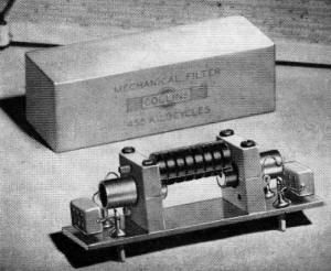
The mechanical filter is shown here removed from its 2 13/16
X 1 X 15/16·inch case. The filter proper consists of the small disks in the center
- each one is carefully machined to the correct dimensions to give the proper mechanical
resonance.
An Approach to the Ideal Selectivity Curve
By Ben Roberts,* W0IEU
For a good solid QSO in a crowded amateur band, we like to hear just one signal
and nothing but that signal. The receiver that will come closest to meeting this
requirement must have a selectivity curve with a flat top, straight vertical sides,
and a bandwidth only wide enough to pass the desired signal. This is the "ideal"
selectivity curve.
Receiver selectivity is usually increased by adding tuned i.f. stages. However,
when this method is used to increase selectivity, even to the point where so much
sideband power is lost that 'phone signals become unintelligible, the skirts of
the selectivity curve may still be broad enough to pass interference from strong
signals a few kilocycles away. Crystal-lattice filters1 offer one approach
to the ideal selectivity characteristic, but they are usually expensive and their
commercial use has been confined to telephone-company applications.
The Mechanical Filter
An entirely new approach to high selectivity is available through the use of
the "mechanical filter," a resonant mechanical device. Shown in the photograph,
it consists of three sections: an input transducer, a mechanically-resonant filter
section, and an output transducer. The input and output transducers are identical
and use magneto-striction to convert the electrical signal to mechanical energy
and vice versa. Three small metal rods are used to connect together the resonant
disks of the filter section. The second disk from each end connects to a transducer
by means of a small metal rod, and the two end disks are secured to the transducer
housings to serve as supports for the filter section.
If you have been waiting for "something new" in the selectivity department, here
it is. By cascading accurately-machined bits of metal, bandpass filters can be built
in the i.f. range that approach in performance the straight-sided "ideal," and this
article describes their operation and their advantages. Unless you are a genius
who has a more practical solution to the problem of crowded bands than the use of
higher selectivity, we're sure you will want to know something about this latest
development.

Fig. 1 - Selectivity at 455 kc. of two mechanical filters
of different bandwidths, shown for comparison with the selectivity obtainable with
nine tuned circuits at the same frequency. The narrower "skirts" and the flat "top"
of the mechanical filters account for their superior performance in crowded amateur
bands.
Magnetostriction, which makes possible the electrical-to-mechanical and mechanical-to-electrical
transformation of energy in the transducers, is a fairly well-known but rarely used
phenomenon. When a highly magnetic substance such as nickel is subjected to magnetic
flux, the shape and volume of the magnetic substance change. The metal will elongate,
twist, or bend. The magnetostrictive transducer used at each end of the mechanical
filter consists of a small coil of wire surrounding a nickel core. Application of
a 455-kc. signal (or whatever other frequency the filter is designed for) to the
input coil causes a magnetostrictive action resulting in a mechanical vibration
of the nickel core. This 455-kc. mechanical vibration is transmitted through the
interconnecting metal rods to the mechanically-resonant disks of the filter proper.
Each disk is mechanically driven by the preceding disk, so that all of the disks
vibrate at 455 kc. The last resonant disk drives the core of the output transducer.
Here the vibrations of the nickel core are changed by magnetostriction into a varying
magnetic field. The output coil intercepts this field and supplies a 455-kc. output
voltage.
In order to avoid a frequency-doubling action that would generate a mechanical
cycle for each electrical half-cycle, a small magnet in the mounting above each
transducer applies a magnetic bias to the nickel transducer core. The electrical
pulses then add to or subtract from the magnetism that already exists, causing the
filter elements to reproduce the input cycle. There is no movement in the mechanical
filter except for the imperceptible vibration of the internal filter elements.
The mechanically-resonant disks of the filter proper have extremely low losses
at their resonant frequencies. Each disk has a Q greater than 2000. Q These high-Q
components exhibit characteristics that make possible application of the theory
of lossless elements to filter design. A mechanical filter can be constructed for
either narrow or broad bandpass without sacrificing its nearly rectangular selectivity
curve. The relatively low Q of electrical elements does not permit the design of
equivalent electrical filters. Typical characteristics obtainable with mechanical
filters are shown in Fig. 1, with the selectivity curve of an i.f, amplifier
using nine tuned circuits (electrical elements) shown for comparison. The transmission
loss of 23 db. or so through the 3-kc. mechanical filter is made up easily by subsequent
amplification by vacuum tubes.
Once the mechanical filter has been constructed, it is enclosed in a hermetically-sealed
case and requires no further adjustment. Connections to the input and output transducer
coils are brought out of the unit on feed-through insulators whose edges are sealed
to the case.
Using the Filter
A receiver using the 3-kc. mechanical filter in its i.f. amplifier handles differently
than one with a conventional selectivity characteristic. As the receiver is tuned
across the band, signals appear and disappear with more than usual suddenness. The
straight-sided selectivity curve makes the band appear less crowded - such a curve
is easier to interpose between two signals without responding to either of them.
Using a steep-sided 3-kc. bandwidth for 'phone reception is by no means standard
procedure, and it requires a bit of explanation. With a good conventional i.f. curve,
like the one obtained from nine turned circuits and shown in Fig. 1, the carrier
frequency must be tuned very close to the center of the selectivity curve. This
is because the carrier level decreases as the receiver is tuned off. As the signal
is moved off the center of the selectivity curve, the carrier level decreases but
one of the sidebands does not. This results in too much sideband for the available
carrier amplitude and causes the distortion (overmodulation at the detector) that
always results when a receiver with a rounded selectivity curve is not tuned "on
the nose." The only way to avoid this distortion is to tune the receiver to the
carrier rather than to a sideband. This is the conventional way to tune a receiver;
however, when we do this, we are splitting our available bandwidth between two sidebands,
although we need to receive only one. Therefore, if a receiver with a conventional
i.f. curve has a 3-kc. bandwidth and is tuned to the carrier, as it must be for
distortionless reception, it will respond to audio frequencies up to about 1500
cycles - not to 3000 cycles as is sometimes assumed. To accept side frequencies
up to 3000 cycles, the carrier must be set off to one side, and distortion will
result, except at very low percentages of modulation. But the curve of the mechanical
filter has a flat top, and setting the carrier off to one side does not substantially
reduce its amplitude with respect to the sideband. By keeping the carrier inside
of the flat-topped selectivity curve, we can tune to either sideband without introducing
the "overmodulation" type of distortion. Since it is no longer necessary to split
the available bandwidth between two sidebands, we can pass a given range of audio
frequencies with a passband only half as wide as would be required with a conventional
i.f. selectivity curve. Since only one sideband is needed for reception of a signal,
setting the carrier at one edge of the passband will still permit us to hear all
of the audio frequencies up to 3000 cycles, when the 3-kc. mechanical filter is
used.

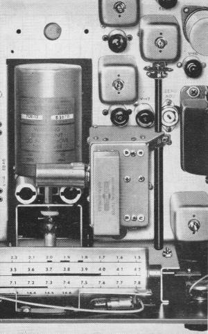
A top view of part of the Collins 75A-3 receiver, showing the
mechanical filter mounted to the right of the tuning unit. Sockets are provided
for an additional filter section if desired, The shaft along the right-hand side
of the filter platform is a double shaft - the outer shaft permits switching between
the two filter units, and the inner shaft is the b.f.o. pitch control.
The 3-kc. filter is excellent for use in reception of s.s.b. signals, when used
with a receiver of good oscillator stability. It has the correct bandwidth for s.s.b.
reception, although the 1-kc. filter can be used when conditions require extreme
selectivity. Under such conditions, the reinserted carrier (b.f.o.) is set about
300 cycles outside the i.f. passband, allowing an audio range of 300 to 1300 cycles
to be received.
The good skirt selectivity of the mechanical filter allows it to reject the carrier
and one sideband of an ordinary a.m. signal, thus converting it to a s.s.b. signal
in the receiver past the filter. The b.f.o. is then set just outside the filter
passband, to coincide with the frequency of the eliminated carrier, for proper detection.
This type of s.s.b.-plus-exalted-carrier reception minimizes the effects of selective
fading and of certain types of noise. Either the 3- or the 1-kc. filter can be used
in this application.
The Filter Applied to the Collins 75A-3 Receiver
The amount of selectivity that is desirable in a communications receiver is a
good subject for debate. Most of us like a very selective receiver, but we also
want faithful reproduction when 'phone signals are in the clear. Development of
the mechanical filter has solved this problem, since to change the selectivity of
a receiver using the filter it is only necessary to cut in a filter of different
bandwidth. The new Collins 75A-3 receiver is supplied with a 3-kc. mechanical filter
and has plug-in provisions for the optional installation of a 1-kc. filter. The
3-kc. filter is ideally suited for all types of 'phone reception including s.s.b.,
and for exalted-carrier reception of regular a.m. signals. Even the 1-kc. c.w. filter
can be used for 'phone reception, as described above. The crystal filter is retained
for phasing out heterodynes.
The mechanical filter is not just an accessory, but is an entirely new development
in communications. It shows promise for use in many applications, including the
simplification of single-sideband transmitter circuits. Presently, development work
is proceeding toward the production of mechanical filters with higher and lower
operating frequencies and bandwidths as required for special applications.
* c/o Collins Radio Co., Cedar Rapids, Iowa.
1) Weaver and Brown, "Crystal Lattice Filters for Transmitting and Receiving,"
Part I, June, 1951, QST.
|


