|
June 1936 Radio-Craft
 [Table of Contents] [Table of Contents]
Wax nostalgic about and learn from the history of early electronics.
See articles from Radio-Craft,
published 1929 - 1953. All copyrights are hereby acknowledged.
|
 This thumbnail image of a
Atwater
Kent Model 776 Automobile
Radio is from the
AtwaterKentRadio.com
website. You can see from the picture that the entire radio was contained in a single
chassis, unlike many models of the day that had the bulky RF electronics mounted behind
the dashboard or under a seat, and the listener interface controls mounted separately in
the dashboard. Below is the Radio Service Data Sheet as it appeared in a 1936 issue of
Radio-Craft magazine. It was one of six such documents that appeared -
without any description or alignment information included as is normal with the
individual, full page data sheets. This thumbnail image of a
Atwater
Kent Model 776 Automobile
Radio is from the
AtwaterKentRadio.com
website. You can see from the picture that the entire radio was contained in a single
chassis, unlike many models of the day that had the bulky RF electronics mounted behind
the dashboard or under a seat, and the listener interface controls mounted separately in
the dashboard. Below is the Radio Service Data Sheet as it appeared in a 1936 issue of
Radio-Craft magazine. It was one of six such documents that appeared -
without any description or alignment information included as is normal with the
individual, full page data sheets.
Atwater Kent Model 776 6-Tube Auto Radio
Radio Service Data Sheet
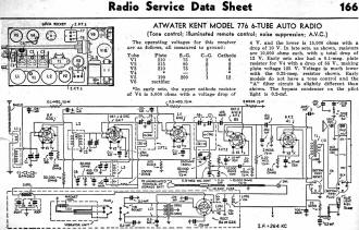 Tone control; illuminated remote control; noise suppression;
A.V.C. Tone control; illuminated remote control; noise suppression;
A.V.C.
In early sets, the upper of V4 is 5,000 ohms with a voltage drop of4 V. and the lower is
15,000 ohms with a drop of 10 V. In late sets, as shown, resistors are 10,000 ohms
each, with a total drop of 12 V. Early sets also had a 0.1-meg. plate resistor for V4 with
a drop of 55 V., making plate voltage 125 V. Voltage is much lower with the 0.25-meg. resistor
shown. Early models do not have a tone control and the "A" filter circuit is slightly different
than shown.· The bypass condenser on the pilot light is 0.2-mf.
|


