|
August 1962 Radio-Electronics
 [Table of Contents] [Table of Contents]
Wax nostalgic about and learn from the history of early electronics.
See articles from Radio-Electronics,
published 1930-1988. All copyrights hereby acknowledged.
|
The
AN/MPN-13|14 mobile radar system I
worked on while enlisted in the U.S. Air Force was designed and fielded around the
time this "Electronic Navigation in Flight" article appeared in a 1962 issue of
Radio-Electronics magazine. It had been upgraded a few times by 1979 when
I was in Air Traffic Control Radar Repairman technical school at Keesler AFB, Mississippi;
however, the original system did not featured a Doppler capability. The fully RF
analog system could not provide air traffic controllers with speed data, but it
did use physical mercury delay lines to provide a stationary target (ground, and
to some degree, rain, clutter) cancellation by inverting and summing a real-time
radar return signal with a copy of the previous return. One of the upgrades to our
system was a digital Identification Friend or Foe (IFF) secondary radar - the TPN-42
- which used the airborne transponders to display squawk codes and altitude information.
It did not have enough computing power to display ground speed and/or airspeed.
Electronic Navigation in Flight
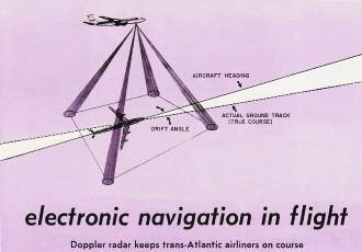
Doppler radar keeps trans-Atlantic airliners on course.
By Victor A. Damora
Airborne electronic navigation systems that determine continuously the speed
and position of an aircraft, automatically and without the aid of information from
ground stations, make it possible for today's long-range high-speed aircraft to
fly anywhere over the surface of the earth any time and under any conditions.
In one type of guidance system, Doppler navigation radar reads drift angle and
ground speed. The results are fed to a velocity triangle computer to obtain the
aircraft track - the actual path of the aircraft over the surface of the earth.
A representative type of Doppler navigation radar is discussed in this article.
First, however, let's review a few factors that were once the exclusive problem
of the navigator, and must now be familiar to the aircraft electronic technician.
We all know of the steering corrections that must be made when rowing a boat
across a moving stream. The boat must be headed upstream in relation to the intended
course to reach a desired destination. The faster the stream and the slower the
boat, the greater the correction required. Aircraft navigation problems with respect
to wind are much the same.

Fig. 1 - Vector triangle for aircraft in flight. Wind speed and
direction are represented by vector 1. Aircraft air-speed, vector 2, drawn from
end of wind-speed vector, is equal to 1 hour of flight. It becomes aircraft true
heading . Vector 3 is resultant of vectors 1 and 2. It is equal to aircraft ground
speed which, in this case, is greater than the airspeed of the aircraft. This is
because the wind helps the aircraft along its intended course.
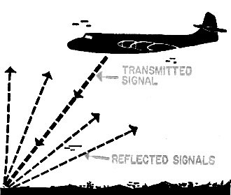
Fig. 2 - Radar signal is transmitted ahead of plane. Part of
signal is reflected to plane. Its frequency will be changed because of Doppler effect.
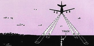
Fig. 3 - On-course flight shows four beams of typical navigation
radar.

Beams misaligned from true course. Beams Band C almost equal;
beams A and D almost at maximum difference frequency. Difference is read to show
plane is drifting sideways.
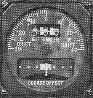
Doppler indicator gives two readings-ground speed in knots and
drift angle in degrees.

Overhead panel gives pilot selected course readings, deviation
left or right, and miles to go to a pre-selected point.
Fig. 1 shows a triangle of velocities that governs the true course of the air-craft
through the air and over the ground. There are six factors to consider:
1. Wind direction.
2. Wind velocity.
3. True course or desired track of the aircraft.
4. Ground speed.
5. True heading.
6. True airspeed.
The ground speed of the aircraft, as shown in Fig. 1, is the resultant of the
true airspeed and the wind speed. The track is the angle between the aircraft's
actual course over the surface of the earth and a reference direction such as true
North. The true heading of the aircraft is the angle between the longitudinal axis
of the aircraft and the reference direction. The drift angle is the angle between
the aircraft true heading and the track. If certain combinations of these factors
are known, it is possible to determine the remaining ones.
Doppler Radar System
The outputs from a Doppler radar navigation system indicate the drift angle and
ground speed. Therefore, only the true heading and true airspeed are required to
solve the triangle of velocities. The true heading may be obtained from conventional
cockpit instrumentation or from a simple inertial heading reference (directional
gyro). True air-speed may also be obtained from conventional cockpit instruments
such as the airspeed indicator (corrected for temperature and pressure).
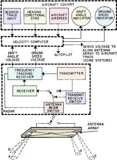
Fig. 4 - Block diagram of typical navigation system.
Doppler radar operation is, of course, based upon the Doppler effect. This effect
causes an apparent change in frequency when a transmitter moves either toward or
away from the receiver or when the receiver moves either toward or away from the
transmitter. If a transmitter and receiver are moving toward one another, the effect
is an increase in frequency. Conversely, if the transmitter and receiver are moving
away from one another, the effect is a decrease in frequency.
If a single pencil beam of microwave energy is transmitted forward from the aircraft,
as shown in Fig. 2, some of the energy will be reflected back to the aircraft, but
at a higher frequency. The frequency change is determined by comparing the received
frequency to the transmitted frequency. The change is proportional to the speed
of the aircraft. This simple system is all we need to obtain ground speed. However,
to learn the aircraft drift angle, more than one beam is required. In most Doppler
navigation systems in use today an antenna array having three or four beams, is
employed.
Fig. 3 shows the four beams of a practical Janus type Doppler navigation radar.
(Janus was a two-faced Roman god that could look in both front and rear directions.)
The forward beam (A) and the diagonally opposite rear beam (D) are paired. The other
forward beam (B) is similarly paired with the diagonally opposite rear beam (C).
The two pairs of beams time-share the radar transmitter and receiver. Time is shared
by switching the antenna feed electronically or mechanically.
Some of the microwave energy transmitted to the ground from a pair of beams is
reflected to the radar receiver through the same beam pair. Since the aircraft is
moving, the energy received in the forward beam (A, Fig. 3) will be higher in frequency
than the transmitted energy and the energy received from the diagonally opposite
rear beam (D, Fig. 3) will be lower. This is caused by the Doppler shift. The reflected
signals received from a pair of beams are mixed to produce a difference frequency.
The process is repeated, using the other pair of beams, and the two difference frequencies
are compared.
The difference frequency of the two beam pairs are alike only when the beams
are aligned symmetrically along the aircraft track. Aircraft heading derived from
cockpit instruments and the error signals developed from any detected difference
between the beam pair differences is used to compute aircraft drift angles. In some
systems the error signals are fed to a synchro system to keep the steerable antenna
aligned with the aircraft track. The angular difference between the antenna alignment
and the longitudinal axis of the aircraft is the drift angle.
The difference signal produced from a single pair of beams is also used to control
a frequency generator whose signal is proportional to the ground speed. Fig. 4 is
a simplified block diagram of one type Doppler navigation radar. The equipment used
by TWA, the first American airline to experiment with the system, is made by Bendix.
General Precision Labs also makes a system, and there may be others.
The Doppler navigation radar, compass system, controls and cockpit displays form
a simple reliable airborne navigation system which is completely independent of
ground aids. Such systems are used in many of today's commercial jet aircraft. They
are tied in with the autopilot, making it possible to fly long distances under autopilot
control without the aid of ground navigational devices, yet arrive right at the
desired destination.
|


