|
|||||||||||||
 |
|||||||||||||
Imaginary Numbers Are a Cinch - Part 2
|
|||||||||||||
When I was in high school, if someone placed me in a classroom where imaginary numbers (whatever they were?) were to be taught - and I was expected to learn about them - I likely would have gone into an anxiety-induced stupor. My plans were to be an electrician, and I was pretty sure electricians didn't need to know about imaginary numbers. By the time I began taking courses toward an electrical engineering degree, I quickly gained an immense appreciation for the power of complex numbers. Anyway... in this second installment of a three-part series, the author educates George (whether real or imaginary - see what I did there?) on the virtues of manipulating complex numbers when dealing with electric circuits which are not purely resistive. The title, "Imaginary Numbers Are a Cinch," omits mention of the real part of complex numbers, but of course they are incorporated in the discussion. Here are Part 1, Part 2, and Part 3. Imaginary Numbers Are a Cinch - Part 2
By Norman H. Crowhurst A few days after our last discussion, George phoned to ask if I could come over and continue where we left off. I arrived at his lab in time to join him for midmorning coffee. He had been trying to figure things out himself since our last talk. Remembering that j x j makes -1, he had deduced that +i x -j makes +1. Was that right? I assured him it was. Then he wrote down a compound multiplication (Fig. 1): 9 + j7 to be multiplied by 7 + j5 and came up with the answer: 63 + j94 - 35.
Fig. 1 - It's not hard to multiply imaginary numbers; plus j times plus j equals minus 1. "You can subtract the 35 from the 63, can't you?" he wanted to know. I nodded. "So the result of multiplying 9 + j7 by 7 + j5 is 28 + j94. Is that right?" he asked. "Certainly," I said. ''I'm surprised you've figured all that out on your own. So why did you call for help?" "I was following up with what you said about division. I tried to check that multiplication by dividing 28 + j94 by 7 + j5, thinking I knew the answer. But I couldn't get very far. Tell me, how do you do it?" Rationalizing "Division isn't so easy. But there's a way to make it easier. It's a process called rationalizing." "So show me rationalizing." "Do you remember what you get by multiplying together A + Band A - B?" I asked him. "Sure do. That's one bit of algebra I'll never forget. It's A squared minus B squared." "Good. So now suppose you multi-ply A + jB by A - jB. What does that make?" "That would be A squared minus jB all squared." He thought a moment, then went on: "But j squared is minus 1, so that's A squared minus minus B squared. As minus minus makes a plus, I guess it's A squared plus B squared. Is that right?" "Correct," I assured him. "Now what's happened to the imaginary part of these numbers?" "There isn't any in the result," he said. "That's interesting, but how does it help with dividing?" "Let's take that division you wanted to do - what was it, 28 + j94 divided by 7 + j5?" I wrote it down as a fraction. "Can you tell me how I could make the divisor, or denominator as it is called in a fraction, just a simple whole number, without changing the final value in any way?" "Oh!" said George, "light's beginning to dawn. If you multiply 7 + j5 by 7 - j5, the imaginary part will disappear. And if you multiply both top and bottom by 7 - j5, overall value is unchanged. Is that right?" He was already doing it (Fig. 2).
Fig. 2 - To divide imaginary numbers, you first write them as a fraction. Then you rationalize the denominator to simplify.
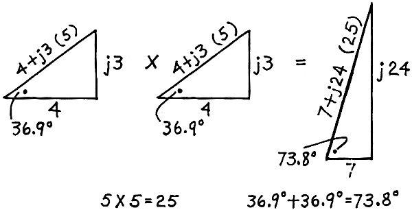
Fig. 3 - Vector diagrams show the effects of using operator j. The angles are added, while amplitudes are multiplied.
Fig. 4 - To divide one vector quantity by another, it's necessary to rationalize the j. Amplitudes follow normal division, but phase angles subtract instead of add.
Fig. 5 - Operator j and the other math tools become useful when you're designing a four-pass filter for a crossover network. Result is a formula for plug-in values. "So now I only have to divide 666 + j518 by 74." He found it easy, because he knew the answer to expect, which was 9 + j7. He was delighted. "Is that rationalizing?" he asked me next. "Rationalizing is the process of making the denominator into a real number, so the numerator can be divided by it to get rid of the complex fraction. What you want is a simple complex number, of the form A + jB." Vector Basics Then I drew approximate scale sketches (Fig. 3) to show a basic result of vector calculations. In every case, multiplying complex numbers produces an amplitude that is the product of the individual amplitudes. The resultant phase angle is the sum of the individual phase angles. "Hey, that's neat," was his enthusiastic comment. Then I showed him how division reverses the process: The amplitude of the result follows normal division, while the phase angles subtract, instead of adding. He worked out an example for himself, using the numbers I picked (Fig. 4). "I'm beginning to see how imaginary numbers will make calculations easier. Now can you give me an example how to use them in a circuit calculation ?" "Right you are. And while we're about it, I'll show you normalizing, another trick that makes math easier. Suppose we want to make a low-pass filter of the kind used in crossovers," and I sketched out what I had in mind (Fig. 5). "We normalize to the working impedance and the cutoff frequency." "Eh? Come again? That sounds awfully complicated." Normalizing "Well, instead of putting in values for working impedance and cutoff frequency, you assume for calculations that they are both 1. You can put in the actual figures for frequency and working impedance later. But it's easier to show you than to try explaining what to do. "First, we assume the filter is terminated with unity impedance. It is shunted by a capacitance that has susceptance of b units and has in series an inductive reactance of a units at cutoff frequency. To design the basic filter, we solve for a and b. Then we can look up values for a particular impedance and frequency on a reactance chart." "That sounds simple and quick," said George. "Let's try it." "Working at the output end, we assume unity voltage and current are delivered to the unity load impedance. This won't happen in a working filter, it's true; the filter will give full output in the pass range, and diminishing output beyond cutoff. Assuming constant output, we must increase input to maintain it. The increase needed (expressed as a ratio or its logarithm) is the same as the attenuation produced in the output when the input is constant. Do you follow all that?" "Yes," George said. I wasn't too sure he did, but he was anxious to see what came next. What Susceptance Is "Right. So we have unity voltage across the capacitance of susceptance b," I went on. "What current will go through this susceptance?" At the word "susceptance" I drew a blank expression from George. I decided to refresh his memory with a few symbols from elementary electronics. I wrote:
Then I reminded him that these 2 components of the admittance (Y) are given the names conductance (G) and susceptance (B).
"Now," I asked again, "what current will pass through this susceptance?" "b units, I suppose," volunteered George. "That's right, at cutoff frequency. What about at other frequencies? Does the current increase or decrease with changing frequency?" "Current in a capacitor increases with frequency," George replied. "So the current in the capacitance will be bf. Is that right?" "Nearly. But if you use f for frequency, you have to remember that cut off frequency is 1, because we're normalizing. You'll avoid confusion if you write x for normalized frequency, which means x is actual frequency divided for the cutoff frequency. x = f / fc "This makes x = 1 at cutoff frequency. That is what we mean by normalizing." Putting j In "So current in the susceptance is bx. Is that right?" asked George. "Except for one thing - phase angle," I replied. "Oh. We put a j in," he said. "But is it +j or -j?" "The important thing is to be consistent. Assume this one is +j. It represents the current in a capacitance. Does this lag or lead the voltage?" "Let's see. It leads, doesn't it?" "Right. So +j means leading and -j means lagging, for this calculation. We write current in the capacitor as jbx. Add this to the output current and tell me what current must flow through the series inductance?" I asked. "Is it 1 + jbx?" asked George in return. "Correct. Now, what is the reactance of the inductance?" "Is it ax?" asked George. "Yes, because inductive reactance is directly proportional to frequency, or x," I answered. "And the voltage drop due to this reactance will be in quadrature with the current through it. Which way?" I asked further. "Leading." George was getting more sure of himself by the minute. "So the voltage drop across the inductance element will be the current through it, multiplied by its reactance," I went on. "That's (1 + jbx) multiplied by jax," cut in George. "So what's the input voltage required to get unity output voltage, which you remember we assumed as a starting point for our calculation?" I'd apparently got a little ahead of George, so he waited for me to explain. "You have the unity voltage at the output, plus the drop in the reactance." I wrote it out. George multiplied this out and rearranged it. He was getting the hang of using imaginary numbers. He had even remembered that (jax) multiplied by (jbx) equaled = abx". "Now, what does all that mean?" he wanted to know next. Phase Angle "Let's see what the expression tells us about this network," I suggested. "First, what's the phase angle?" "We did that the last time. It's the ratio of the imaginary part to the real part, and then you find the tangent on the slide rule. Isn't that it?" "Correct. Now, how does this angle change as frequency, represented by x, varies? At some frequency, when abx'' = 1, the denominator goes through zero. What angle is that?" "90°," volunteered George, "because the real part is zero - it's all imaginary, or in quadrature." "How can we make this happen at cutoff where x = 1 ?" "By making ab = I?" suggested George. "Right. Now, when x is much smaller than 1, meaning that frequency is well below the reference cutoff frequency, x squared will be a still smaller fraction. For example, if x is half, x squared is quarter; if x is one fifth, x squared is one twenty-fifth." George was with me. "Now assume that a is slightly larger than unity. Then abx2 will be much smaller than 1," he said. "The real part will be nearly 1 and positive, and the imaginary part will be smaller than 1, so ... " He didn't quite know what this proved.
Fig. 6 - The phase angle of the circuit changes as the operating frequency does.
Fig. 7 - When the phase angle is not 90°, figuring the value of input voltage to the filter requires these calculations.
Fig. 8 - The product of Fig. 7 can be simplified into this decibel expression. I said, "Because both real and imaginary parts are positive, the angle is something less than 45°, because the ratio is fractional - less than 1." He saw that (Fig. 6). I went on, "As x approaches 1, abx2 will still be less than 1, and ax will get bigger than (1 - abx2), so the angle will approach 90°. Then we pass through 90° when (l - abx2) is zero. Beyond that, (1 - abx2) is negative, so the tangent ratio is negative, indicating an angle over 90°. As x gets larger than 1, x2 gets much larger than 1, so the ratio is almost the same as x/x2, or 1/x." George had followed this and saw the value of approximating in this way, to see where the angle "goes" without detailed calculations. I went on. "Now about amplitude. For the 3-dB point to coincide with the 90° phase point and cutoff or crossover frequency, where x equals 1, what else must we fix?" "Is this expression," George pointed to (1 - abx2 + jax) in Fig. 5, "in voltage, current, or power?" "We decided, when we started, that it represented input voltage needed to produce unity output voltage," I replied. "So the 3-dB point means we need the input voltage to be root two, or 1.414 times output voltage. Is that right?" "Yes." "Then with (1 - abx2) as zero, the jax part must be 1.414. The j merely identifies the 90° phase shift; also x is 1 at cutoff or crossover, so a must be 1.414. Right?" "It certainly is. This means the reactance of the inductor must be 1.414 times the output load impedance at cut-off or crossover frequency." "Well, that's not too hard to figure," said George. "Now what about the capacitor value?" "Just remember that b is in susceptance at cutoff frequency. So reactance would be 1/b." George was figuring this out. "If ab has to be 1, then b must be 1/a, or 0.707. But then we'll use a reactance chart to find it, so we'll use 1/b, which is a, or 1.414. So both a and b are reactances of 1.414 times the output load value, at crossover frequency. Is that right?" I nodded. George was already showing a flair for taking shortcuts, which was fine. Filter Design "It's beginning to make sense," he said. "But the filter that started all this discussion is much more difficult to figure out, isn't it?" "Not so hard," I told him. "We've already got the configuration. But before we go further, we should explore the response of this simple filter in a little more detail. In that quick calculation, we did two things for the sake of convenience: "1. We assumed it is what we call a constant-resistance type - by which we mean, among other things, that the 3-dB and half-phase points coincide at cutoff frequency. "2. We considered attenuation only at one frequency. To provide background for more work, we need to figure out more details of the phase and amplitude responses at some other frequencies. "For example, what is the amplitude of the input voltage, or attenuation factor, when the phase angle is not conveniently 90°, and maybe when this doesn't happen to coincide with the 3-dB point?" George didn't know where to begin, now, so I continued. "It's the vector sum of the quadrature components, (1 - abx2) for the real part and jax for the imaginary or quadrature part. That's the square root of the sum of the squares, remember?" That set George off, squaring (1 - abx2) and ax, and adding the parts together, according to terms of x2 and x4 (Fig. 7). Then he put the whole thing under a radical sign. "Actually, if you're working in dB you don't have to go that far," I told him. "The magnitude of the resultant vector is a voltage attenuation ratio, which converts to dB as 20 times the log of this ratio. So don't bother taking the square root. The vector is simply 10 times the log of this sum of the squares." (Fig. 8) Another Problem I noticed that time was creeping up on us. I had to leave. "Time for me to get going, George. See if you can figure out what makes the 3-dB point come at x = 1 and also the conditions which would make the response show a peak or a loss greater than 3 dB when x = 1. Did you do any calculus in school?" "Yes, I did," replied George. "It's rusty, because I've never used it since. You mean I'm going to put it to use at last?" "Yes," I said as I pulled on my coat. "Next time." To Be Continued
Posted August 27, 2024 |
|||||||||||||
 |
|||||||||||||
|
|||||||||||||
 Part 2 of a series - More about some handy math
tools - including operator j - and how they're used to design electronic filters.
(Part 1 appeared May 1967)
Part 2 of a series - More about some handy math
tools - including operator j - and how they're used to design electronic filters.
(Part 1 appeared May 1967) 

|
||||||||||||||||||||||||||||||||||||


