|
September 1960 Radio-Electronics
 [Table of Contents] [Table of Contents]
Wax nostalgic about and learn from the history of early electronics.
See articles from Radio-Electronics,
published 1930-1988. All copyrights hereby acknowledged.
|
Based on three major
stories on tunnel diodes in 1960 issues of Radio-Electronics magazine,
you might think the relatively new negative resistance device was a big deal. It
was. Known also as an Esaki diode, the tunnel diode, named after its inventor,
Leo Esaki, in 1957, is a two-terminal
semiconductor device which exhibits negative resistance over a certain range of
voltage and currents, making it useful as an oscillator and amplifier. The tunnel
diode works on the quantum
tunneling principle. Its cost compared to a transistor is much lower, and its
operational frequency is much higher than that of a transistor (at least it was
so back in 1960 and for a couple decades afterwards). Big plans were made for using
tunnel diodes as local oscillators and even amplifiers in radios and radars. Their
relatively low voltage and current handling ability caused them to be preferred
less than the high power handling
Gunn diode, which emerged
just a few years later.
The Tunnel Diode Story
(7/60), A
Tunnel Diode Oscillator (9/60),
The Tunnel Diode Really
Works (10/60)
A Tunnel Diode Oscillator
 By William Grossman* and Marvin Friedman* By William Grossman* and Marvin Friedman*
The tunnel diode promises to be the most important achievement of the semiconductor
industry since the transistor was invented. Circuits using tunnel diodes are already
showing themselves superior to those using transistors and vacuum tubes, in several
applications.
Let us connect a conventional p-n junction diode (such as the 1N34) in the circuit
of Fig. 1. The center-tapped potentiometer allows us to either forward- or reverse-bias
the diode. If we vary the potentiometer setting and plot the change of current as
the voltage is varied, we get the typical p-n junction-diode curve (Fig. 2).
The curve shows that the diode has a low internal resistance when forward-biased
(region A to B in Fig. 2) and a high resistance when back-biased. This is the area
from A to D. Increasing either the forward or' back bias of the diode increases
the current (though the increase is very small in the reverse direction). We can
say that the diode has a positive resistance when either forward- or back-biased.
Tunnel-Diode Curve
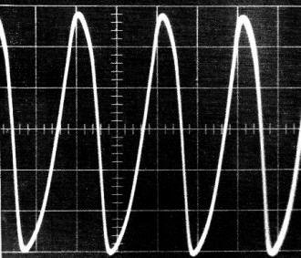
Photograph of oscilloscope tracing (using 5,000-cycle coil).
Scope is connected across tuned circuit.
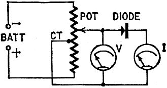
Fig. 1 - Setup for plotting diode current as a function of voltage.
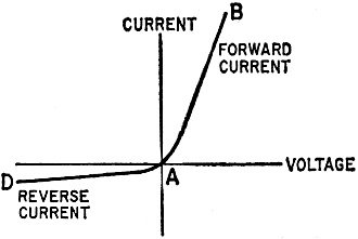
Fig. 2 - Current-voltage characteristic of a typical p-n junction
diode.
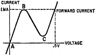
Fig. 3 - Current-voltage characteristic of Esaki tunnel diode
(GE No. ZJ-56A).
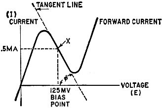
Fig. 4 - Slope of characteristic around point X indicates negative
resistance.
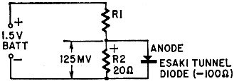
Fig. 5 - Circuit for biasing tunnel diode from low source resistance.
The tunnel-diode oscillator. The L-C combinations are attached
to pin jacks for easy band changing.
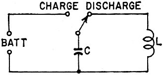
Fig. 6 - A basic L-C circuit.
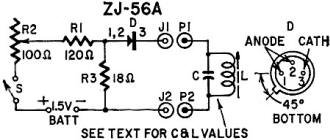
Fig. 7 - Schematic of tunnel-diode oscillator. See text for values of L and C.
R1 - 120 ohms
R2 - pot, 100 ohms, linear taper
R3 - 18 ohms
All resistors
1/2 watt
C - see text
S - spst switch on R2
D - 1-ma-peak tunnel diode
(General Electric ZJ-56A or equivalent)
Batt - 1.5-volt penlight cell
J1,
2 - tip jacks
P1, 2 - tip plugs
Transistor socket
Fuse clip for battery
Knob and phenolic board
Now suppose we insert an Esaki tunnel diode (General Electric Co. No. ZJ-56A)
in the same circuit and plot the current as the voltage is varied. The curve is
shown in Fig. 3. The current change is vastly different from that of the 1N34.
As forward bias is increased, the current rises rather quickly to a peak (point
B). As forward bias is further increased the current decreases abruptly to point
C, then starts rising again. The current through the tunnel diode increases with
an increase m voltage in the region from A to B. This means that it has a positive
resistance in this range. From B to C in Fig. 3, there is a decrease in current
for an increase in voltage, or a negative resistance. We can say that this tunnel
diode has a negative resistance characteristic when it is forward-biased at any
voltage between Band C.
* B & K Manufacturing Co.
If we draw a line tangent to the curve at point X in Fig. 4, we can see that
the tangent or slope (θ) of the curve is negative. (A negative curve, in mathematics
is one whose vertical value, or distance from the base line, decreases as its horizontal
distance to the right from the origin increases. This is analogous to the electrical
decrease in current with increase in voltage.) The value of the tangent is the current
divided by the, voltage at the tangent point. This equals the diode's negative resistance.
Bias
We want to bias the tunnel diode in the negative-resistance portion of its characteristic
(Fig. 4, point X). When so biased it can oscillate or amplify.
Oscillator, audio to rf ranges
Active element - a tunnel diode
Power
source - penlight cell
Values given for four frequencies, others may be built
as desired.
A typical tunnel diode has a negative resistance of approximately -100 ohms when
biased in its negative resistance region. Approximately 125 millivolts are required
to bias the diode. The current drawn by the tunnel diode (when biased at this point)
is approximately 0.5 ma. If our source of voltage is a 1.5-volt battery, we require
a series resistor of about 3,000 ohms. Since our diode has a negative resistance
of 100 ohms, the sum of the series resistor and diode's negative resistance is 2,900
ohms. Thus the diode's negative resistance has been cancelled by the series dropping
resistor. To overcome this difficulty, the biasing voltage is developed across a
resistance source less than the absolute value of the diode's negative resistance.
The diode power supply then is as shown in Fig. 5. When this circuit is used, the
diode has a net negative resistance of 80 ohms.
If an external circuit is connected to the diode and the resistive losses in
the circuit are less than 80 ohms, the circuit can oscillate because the external
losses are overcome. If an external circuit has losses equal to the negative resistance,
the circuit is stable and can amplify.
By adjusting circuit losses, it is possible to use the same diode for oscillation
and amplification at different frequencies. This action is like that of vacuum tubes
or transistors in reflex circuits, now becoming common in experimenters' 1- or 2-transistor
"shirt-pocket" radios.
Transistors and vacuum tubes depend on the control of charge carriers (electrons
or holes) by a third element (a grid or base) . This process takes finite time and
is inherently noisy. These factors limit the frequency at which conventional devices
can operate. The tunnel diode depends on a unique "quantum-mechanical" tunneling
of charge carriers through the diode junction. This effect apparently takes place
at close to the speed of light. Thus the tunnel diode's theoretical upper frequency
limit is extremely high.
Resonant Circuits
Now that some of the mystery surrounding the tunnel diode has been clarified,
we will attempt to create a circuit that will take advantage of its negative resistance.
Fig. 6 shows a parallel-resonant circuit consisting of an inductance L and capacitor
C.
If the capacitor is placed across the battery (and allowed to charge) and then
reconnected to L, it will discharge through the inductance. Current flowing in L
will cause a magnetic field to be built up around the coil until the capacitor has
discharged. The field will then collapse (since the magnetic field can be maintained
only while current is flowing). The collapsing field will induce a voltage in L
which will cause current to flow back into C (recharging it). This process would
repeat itself again and again if there were no losses in the circuit) at a rate
called the resonant frequency. In practice, however, no capacitors or coils are
loss-free. These losses appear in the circuit in the form of resistance and consume
power.
To make this charge and discharge process continuous, power must be supplied
to the circuit in amounts equal to the power consumed by R (the loss resistance).
When this is done, the circuit oscillates. In practical vacuum-tube oscillators,
enough of the output is fed back into the input circuit to overcome the resistive
losses of the resonant circuit. This can be expressed by stating that the energy
fed back overcomes the positive resistive losses. Thus the fed-back energy can be
called - R.
Practical Oscillator
The tunnel diode has a negative resistance, or -R, characteristic. If the negative
resistance is greater than the positive resistance of the circuit, we have a diode
oscillator. Fig. 7 shows the circuit of such an oscillator.
The battery supplies the necessary bias voltage to set the operating conditions
of the diode. R1, 2 and 3 are equivalent to R1 and 2 of Fig. 5. The diode is connected
across the resonant circuit. Since the negative resistance of the diode is greater
than the sum of R3 and the losses of the tuned circuit, the circuit will oscillate.
The table shows values of L and C that will enable the circuit to oscillate over
a wide range of frequencies.

* Reading from the top down, J. W. Miller Nos. 6314, 4408 and 4403
If C is a variable capacitor, it is possible to tune the oscillator to various
frequencies. This circuit will oscillate at a very high frequency whose limit is
dependent on the value of L and C. The diode used, No. ZJ-56A, has the positive
element connected to pins 1 and 2 and the negative element is pin 3. Two leads are
used for the anode to minimize lead inductance. If this inductance is too large,
it restricts the upper frequency at which the diode will oscillate.
Adjustments
Adjusting R2 is all that is required to establish proper bias for the diode.
The oscillation can be detected by connecting an oscilloscope across the tuned circuit.
If a scope is not available, tune a receiver to the approximate frequency and adjust
R2 while searching for the signal.
Construction
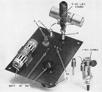
The oscillator is constructed on a piece of phenolic board. A transistor socket
is used for the diode (in case the builder wishes to use the same diode for other
applications). Power is supplied by a single penlight cell mounted in a fuse clip.
An on-off switch (mounted on the 100-ohm pot) is used to prolong battery life (which
should be in excess of 50 hours).
The tuned circuit (a capacitor-coil combination selected from the above table)
is plugged into the two pin jacks. This arrangement allows quick frequency shifting
when desired.
The frequency stability of the oscillator is excellent and is limited primarily
by the stability of the coil and capacitor.
Posted July 1, 2024
|


