|
Super-low-noise-figure receivers
are absolutely essential in radio astronomy work. The need has driven major advances
in the state of the art of cryogenically cooled front ends with noise temperatures near absolute zero.
Antenna technology has also benefitted from radio astronomy due to the need for
precision steering and narrow beam widths. Phased arrays (aka interferometers) for
interstellar targets requires that element spacing be large enough to require separate
antennas as the elements, which creates a very large effective aperture, hence greater
angular resolution. Networks located continents apart are synchronized with the
use of atomic clocks to allow signal time of arrival and therefore phase to be accurately
measured. This story gives some of the early efforts.
Related articles: "How
We Listen to Stars and Satellites" - January 1958 Popular Electronics,
"Radio Astronomy
and the Jodrell Bank Radio Telescope" - February 1958 Radio & TV News,
"Radio Astronomy -
Low Noise Front-Ends" - June 1954 Radio & Television News, "Radar
Explores the Moon" - May 1961 Popular Electronics, "Cosmic Radio
Signals from Sun and Stars" - March 1948 Radio-Craft
Radio Astronomy

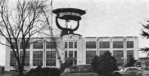
Fig. 1. One of the parabolic reflectors being used with
the interferometer now in operation at Cambridge, England (right).
By Dr. F. G. Smith
Astronomers are using new tools and techniques to provide the answers to some
age-old riddles of the universe.
In 1942 radar operators in England began to report a new kind of jamming observed
on their meter-wave-length receivers. Weak radar echoes became lost in the "grass"
on the (radar) screen, as if swamped by "noise" from a powerful transmitter. In
the Army Operational Group, a scientist named J. S. Hey - later to be known as one
of the pioneers of the new science of radio astronomy - examined the reports. He
established that the source of the "jamming" was no enemy station, but the sun,
and he noticed that at that time an exceptionally large sunspot was crossing the
sun's face.
Radio amateurs can detect this radiation from the sun during periods of sunspot
activity, and even television screens are affected by it, but few people know that
the sun and some other celestial objects are radiating short radio waves continuously.
The first observations of this steady radiation were made in 1932 by an American
radio engineer, Jansky, who was investigating the level of noise picked up by a
sensitive receiver on a frequency of 20 mc. He found that a directional antenna
gave a greater noise signal when pointing at the constellation of Sagittarius, in
the brightest part of the Milky Way, than in directions away from this high concentration
of stars. Ten years later, a radio amateur, Reber, built a parabolic reflector antenna
30 feet in diameter, in his own yard, and used this to make a map of received signal
strength on frequencies up to 500 mc. over a large part of the sky.

Fig. 2 - Array of full-wave dipoles at 3.7 meters.
This array is one-half of an interferometer for detecting radio stars. See text
for full details.

The 600-inch "radio telescope" installation at the Naval Research
Laboratory which is being used to study radio "signals" from the sun, moon, and
stars. Scientists use this research tool to extend man's knowledge of the universe
and to assist in forecasting the conditions for radio communications work.

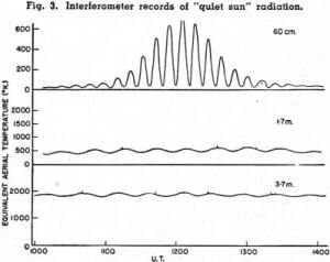
Fig. 3 - Interferometer records of "quiet sun" radiation.

Fig. 4 - Part of interferometer recording showing the presence
of several of the minor "radio stars."

Fig. 5 - Section of record with high sensitivity showing
intense source in Cassiopeia. See text for details.

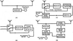
Fig. 6 - (A) How two similar antennas, spaced several wavelengths
apart, are used to detect radiation from the sun. (B) Use of a phase-sensitive detector
to eliminate receiver noise. (C) Improved version of the circuit shown in (B) in
which the antenna noise is continuously compared with the noise generated from a
controllable local source. a noise diode. (D) A pair of antennas connected in a
radio interferometer with a device for reversing phase of the signal from one antenna
periodically.

Fig. 7 - Parabolic reflectors used in an interferometer
for accurate direction finding.
Then came one of the most startling discoveries, again first hinted at by J. S.
Hey. Workers in Australia and England found that the radio waves picked up by Jansky
and Reber came, not only from the Milky Way but also from some quite definite points
in the sky, as though individual stars were transmitting to us. But there were no
bright stars at these points, and it was not until 1952 that these "radio stars"
were identified with visible objects in the sky; even then the objects were so faint
and inconspicuous that it needed the 200-inch Hale telescope at Mt. Palomar to find
them. Many astronomers have become interested in this new science as an extension
of astronomical techniques, and radio-astronomy is now being put to use in many
parts of the world extending our knowledge of the solar corona, interstellar gas,
nebulae, and even of our own ionosphere. In this article we shall be concerned less
with the results than with the methods, since the problems of technique are of great
interest and are not well known.
The two main problems facing the radio-astronomer wishing to study radio waves
from some object or region in the sky are simply stated. First, the power available
in his antenna is usually not greater than about 10-16 watt. Second,
the beam width of his antenna is usually vastly greater than the angular size of
the object, and the radiation picked up may well have come from many other objects
in this region. Both these difficulties, of signal strength and resolving power,
clearly call for large antenna systems and the radio astronomers are, in fact, building
large antennas for this work. In Manchester, England, there is now under construction
a very remarkable parabolic reflector antenna. This will be 250 feet in diameter,
and it will be so mounted that it can be directed towards any part of the sky. The
reflector will be made of wire mesh, and the accuracy of its surface will be such
that it can be used on wavelengths as short as a half meter or less. But many observations
can be made with much smaller antennas by using the principle of the radio interferometer.
If two similar antennas spaced several wavelengths apart and both directed towards
the sun, are connected to the same receiver, as in Fig. 6A, it is possible
to distinguish the radiation received from the sun against a background of radio
waves from the stars behind it, although this background may be several times more
intense than the solar radiation. The records of total power received from such
a radio interferometer as the sun moves slowly across the sky would be like those
in Fig. 3, showing some actual records on various wavelengths. In each the
sinusoidal variation of signal is due to the sun passing in and out of the interference
zones of the spaced antennas, whereas the steady signal, most evident on the longer
wavelengths, is from the extended source of the Milky Way background. An improved
method of recording recently used makes a record of only the sinusoidally varying
signal, giving the intensity of the solar radiation without any confusion from the
background radiation. The method of achieving this, known as phase-switching, will
be described after we have examined more closely the problem of detecting these
exceedingly small signals.
The character of the signals received from the sun and the stars is exactly the
same as that of "receiver noise." If we connect the input of a receiver first to
an antenna and then to a dummy load, the difference in signal may be demonstrated
as a change in the output of a detector circuit, but this change may be only a few
percent of the output, most of which is due to the receiver noise. It is necessary
to record this difference without including receiver noise, and this is achieved
in the schematic of Fig. 6B. The use of a phase-sensitive detector enables
a long time constant to be used in the output circuit, and the smoothed output records
the difference between the two levels of noise. An improvement is again made in
Fig. 6C, where the antenna noise is continuously compared with the noise generated
in a controllable local source, in practice, a noise diode. The output from the
local source is automatically adjusted to equality with the antenna noise, and a
record of the current in the diode gives a direct record of antenna noise unaffected
by the characteristics of the receiver. The records in Fig. 3 were made in
this way.
These methods of detecting small noise signals have been widely used in the measurement
of the total noise power received at an antenna. But in radio astronomy it is often
necessary to select only that part of the noise which is coming from a small source
in the sky, perhaps a radio star or a sunspot, and to disregard a large proportion
coming from a diffuse background of other sources. A new method of detection is
then used.
In the schematic of Fig. 6D a pair of antennas is connected in a radio interferometer
with a device for reversing the phase of the signal from one antenna periodically.
The lobes of the interferometer radiation pattern then shift by a half lobe width,
due to the phase shift, and the signal from a source smaller than the lobes of this
pattern will change periodically by an amount depending on its position in the pattern.
Again a phase-sensitive detector is used to measure this periodic change in output.
In Fig. 4 we see the recorded output of such a phase-switching receiver connected
to a large interferometer operating at a wavelength of 3.7 meters, shown in Fig.
2. The output is centered on zero, and the groups of oscillations each record the
passage of a radio star through the antenna receptivity pattern as the earth rotates.
This method of recording radio stars has been used in the accurate location of some
of the most intense radio stars. A record from the intense radio star in Cassiopeia
using part of the same interferometer is shown in Fig. 5.
The interferometer in Fig. 2 is located along an east-west line so that
each radio star is detected as it crosses the meridian, a line from the zenith to
the south point. The time of this crossing, found from the record, gives the position
of the star in the sky. The timing may often be carried out to an accuracy of about
0.1 second, but unfortunately the actual position of the star cannot be determined
quite as accurately as this. For one thing, the position of the interferometer axis
must be known, and with the antennas of Fig. 2 this cannot be defined to better
than about 2 minutes of arc. The interferometer in Fig. 7 was specially built
for such work, and the line joining the bearings of the two parabolic reflectors
was determined to 10 seconds of arc. These reflectors are two of the antennas of
the "Wurzburg" radar set much used by the Germans during the war. They are 27 feet
in diameter, and the two are mounted 900 feet apart, 200 wavelengths at 1.4 meters,
the wavelength used in the most accurate direction finding experiment yet made.
With this interferometer, a radio star in the constellation of Cassiopeia was located
within an area only 10 seconds by 30 seconds of arc. The position was given to astronomers
at Mt. Palomar, who found with the 200-inch telescope a new type of nebula exactly
in the right place.
This new branch of science is certainly providing new tools for the astronomer
in his survey of the heavens, but it may also prove to be a useful approach to some
studies of the ionosphere. When Hey first detected radiation from a radio star,
he distinguished it from the background because the signal was fluctuating in a
peculiar way. This effect we now know to be very similar to the scintillation, or
"twinkling," of ordinary stars. It is caused by refraction in irregularities in
the earth's ionosphere, through which the radio waves pass, and by studying the
fluctuations in signal it has been found that the irregularities are in the upper
part of the F-region, inaccessible to pulse-sounding methods. It appears that the
top of the F-region occasionally becomes corrugated, to an extent of about one percent
of its total depth, the wavelength of the corrugations being about 5 km. The whole
structure is drifting across the earth at a speed of several hundred miles-per-hour,
and the effect on the ground is similar to the moving pattern of sunlight on the
bottom of a swimming pool when waves disturb the surface. The cause of this ionospheric
disturbance is still unknown.
Another useful way of investigating the ionosphere has been suggested. As the
radio waves from a radio star pass through the ionosphere they may be refracted
in such a way as to make the star appear in the wrong position. The amount of this
displacement may be measured, and depends primarily on the total number of electrons
in a vertical column right through the ionosphere. Pulse-sounding methods are not
suitable for this measurement, and it is likely that understanding of the ionosphere,
still full of mysteries, will be helped by these new experiments.
The most exciting discoveries of radio astronomy have been in the search for
sources of radio waves in our galaxy and in extragalactic nebulae, and this search
is being pursued with great vigor in several places. The new Manchester antenna
will be used in this work. Recently some details were published on a new antenna1
at the Ohio State University designed to carryon the search. There is, however,
a large interferometer antenna now in operation at Cambridge, England, which may
well be called the largest radio-telescope in the world. Its parabolic reflectors
cover an area close to 50,000 square feet. Results from a survey of radio sources
in the Northern sky should be available in a few months' time. No description of
this instrument has yet been published, and a picture of one of the reflectors in
Fig. 1 is the only one available as yet. It is hoped that this instrument will
provide some further clues to the solutions of the great problems "What are radio
stars?"; "How many are there in our galaxy?"; "Do other galaxies have radio stars
like ours ?" - questions we may hope to have answered in only a few years from now.
Reference
1. Kraus , J. D. and Ksiazek, E.; "New Techniques in Radio Astronomy," Electronics,
September 1953
Posted September 10, 2019
(updated from original post on 7/7/2013)
|


