|
Thanks
to Internet, there has never been a better opportunity to be able to step back in time and
reclaim some of your past indulgences. A lot of guys are using resources like eBay and
specialty website forums to search for items remembered from days of yore. Although I can't
imagine how it can be so based on my slacker personal habits as a teenager, there are still
available a fairly large number of hobby type items that I recall owning (and subsequently
destroying or losing) - many in like-new condition and some even in their original, unopened
packages. I, for one, have bought numerous model airplanes, boats, engines, and rockets,
Erector Set items, Peanuts paraphernalia, magazines, electronics stuff, and even albums from
my teenage era in the late 1960s and early 1970s. If you are about my age or even older,
chances are you have either done some of the same, or have considered doing so.
Bob Davis, an
RF systems and circuits designer of many years, has submitted accounts of a couple radio
restoration projects he has undertaken, and now he has sent this one which tells of his
experience tracking down and acquiring the first shortwave radio like the one he had as a
teenager in Iowa. It reads like a chapter out of an autobiography, but also incorporates a lot
of good technical talk including some hints regarding good strategies for finding information
that might not be so easy to access in your initial Google searches. The photos of the radio
chassis and circuit components are excellent. Enjoy!
Here are Bob's restoration stories for his
Midland and
Lloyds
shortwave radio, his RCA 86T, and a few
other radio restoration
projects.
Midland 10-561 Shortwave Radio Restoration
Article and images by Bob Davis
It was sometime in the early 1970s and before the days of the Internet that one of the best
ways to stay tuned to what was going on in the world around you was by shortwave radio.
At the time the shiny boxes with a multitude of dials were greedily eyed as I flipped through
the pages of the magazines and catalogs I received by mail. One could tape 25 cents to a post
card placed inside an envelope and send it by mail to an address in Kansas City, MO; Chicago,
IL; New York, NY; Los Angeles, CA; and some place in the middle of nowhere called Benton Harbor,
Michigan and receive (within an eternity of time of 8-10 weeks) glorious publications in return
post that were chock full of things I found I 'desperately needed. '
A 12-year- old with a paper boy 's budget was no match to purchase the legendary sets available
at that time. I was resolved to buy a receiver, even if my budget was less than 100 bucks. I
put aside my dreams of owning a Heath, Hallicrafters, Drake, Collins, or Hammerlund brand, settling
on the cheaper radios produced by Asian vendors.
|

The Venerable LLOYDS 9N11A Shortwave Radio (as I remember
the Aldens catalog ad)
|
Perusing the radio catalogs brought forth names like LLOYDS, Knight, Panasonic, Juliette, Sony,
Midland International, Hitachi, Sanyo, Lafayette, and Jade. After reading all I could in the sales
text below the color or black and white photographs, weighing the features of each, the price
loomed at the bottom of the page, usually more than my budget could support, so I pressed on.
One day, Mom received a catalog from Aldens (long defunct, and before they went away merged
with the more famous Gamble Stores), in true “Christmas Story Red Rider Fashion Glory” a LLOYDS
8 Band Shortwave receiver smiled at me from the back cover. It was less than 90 bucks (if memory
serves me), a “special sale.” I negotiated with Mom, and pulling hard earned money from my paper
route stash, the order was placed.
After waiting for what seemed like an eternity, I came home from school one day with my Mom
greeting me at the back door, Aldens box in-hand. I immediately opened the box and to my amazement
and dismay found another model of radio inside. A Midland International logo on the box informed
me that the Lloyds 9N11 was not what was sent. The old switcheroo, I wasn 't too impressed.
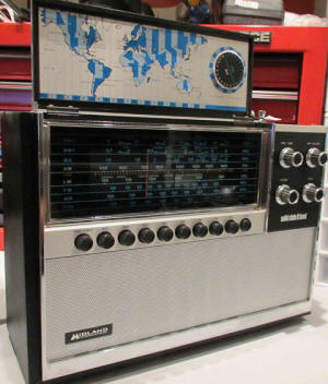
The Midland International 10-561 Shortwave Radio (what was in the box..) |
I discussed the issue with Mom and decided it was worth opening the sealed Midland box instead
of sending the whole thing back and asking for the Lloyds I had ordered. I decided that the picture
on the Midland box looked something like the Lloyds radio I had ordered, so I freed the radio
from its carton.
Upon first visual investigation the Midland 10-561 radio seemed to be very similar to the Lloyds
9N11 and had the additional benefit of a dial cover. The Midland 's knobs had the same function
as the Lloyds, the AC/DC switch was inside instead of on the front panel, the dial had blue markings
instead of orange, and the unit was a bit smaller. I thought, perhaps this is an upgrade
and a newer model?
I fired up the Midland and took it for a spin across all 8 bands. I was immediately smitten
and told Mom we 'd keep the Midland and I was satisfied with the substitution. Many hours were
spent listening to the Midland as the QSL cards I sent for as a result of successful DX covered
my bedroom walls. The Midland 's greatest achievement was copying a 10 kW Radio Australia broadcast
from Melbourne (as the QSL card stated).
Time passes on, and my teens and 20s came and went. The Midland short wave radio met its end
one day after I left home as it was being used by other family members. I don 't quite know what
happened to it, I just know it was pitched for some reason.
Now let 's fast forward to the 2010s and a nostalgic radio engineer looking at eBay…..
I found a Lloyds 9N11B-120A radio that looked to be in decent shape and ordered it. I took
the Lloyds to the radio bench and gave it a full restoration and alignment using test equipment
undreamt of by its designers in the early 1970s. The Lloyds unit is a great performer for a radio
built using standard, lumped element IF filters (i.e. not as narrow or precise of a bandwidth
as one would fine on a Ham rig that uses Collins mechanical filters or crystal filters in the
IF) and consumer grade mid century transistor radio technology.
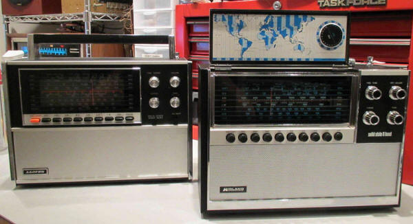
Both Radios Placed Side by Side (Lloyds is on the left, Midland is on the right) -- Twins?
Howard Sams (or whatever they are now…) had a Photofact for the 9N11B-120A in their TSM-139
(and for 22 bucks (YIKES!) you can have your own PDF copy of it via their website). The Photofact
also has alignment instructions which came in very handy (down to the color of the slugs of the
tunable inductors).
I noticed the inside of the 9N11B-120A had a strong resemblance the inside of the Midland 10-561
I had when I was a kid. Being a radio geek from long ago, the back of the Midland 10-561
was off more than once for modifications and experiments.
I rebuild tube type radios for a hobby with a mid-century transistor set thrown in from time
to time for good measure. One night, I was searching eBay for my next restoration victim and came
across a Midland International 10-561 set that looked to be in pretty good cosmetic condition.
I ordered it. Later that week, another 10-561 came up on eBay from another seller that was even
prettier, so that one found its way home too.
When the restoration process for the two sets started, I noticed one set had low output volume
(due to an open capacitor in the audio section) and the other had some difficulties getting the
local oscillator to light up reliably on the higher VHF bands (remedied by a thorough cleaning
of the selector pushbuttons with Caig Fader Lube). Both repairs were performed without a schematic
as many years of experience fixed the LO issue with a visual look at the PC board (broken trace,
a common problem with these vintage transistor sets) and signal injection of hum through the audio
stages with my trusty x-acto knife as a probe quickly uncovered the bad cap. (Only use the x-acto
knife hum injection trick on a battery operated transistor set please, doing so on an AC “hot
chassis” transistor set or a tube set could be downright lethal.)

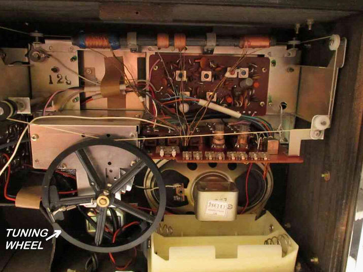
Back Cover Removed from the Lloyds Receiver Showing Large Tuning Wheel |
I performed several other minor repairs before I put both units in their cases and got ready
to align them. During the electronic restoration, I was unable to locate a Sam 's Photofact for
the Midland set on the Sams website (or a suitable schematic anywhere else on the Internet for
that matter). Finding a schematic or a service manual became somewhat of a treasure hunt.
I was successful in finding what I needed and wanted to share my results of that hunt on-line
(if Kirt would be so kind to publish this) so that others will gain benefit from my efforts.
From what I can tell, a company called Koyo Denki out of Japan (?) manufactured many transistor
sets which were rebranded by U.S. companies. My research found that the Lloyds 9N11B-120 receiver
could also be found carrying a Koyo Denki, and Commodore tag.
The Lloyds receiver has a tell-tale tuning wheel which is visible through the opened battery
cover. Some pictures follow of my receiver showing this detail.
A good example of another radio that has this tuning wheel and the Lloyds front panel is shown
next. Commodore was a brand I 'm not too familiar with; I am sure some long defunct catalog
company had it as their store-brand or the like. Note the front panel showing pushbutton band
selection and the four main controls of Tuning, Fine Tuning, Tone, and Volume On/Off for the sets
that are shown. Also note the rear views of the radios with the battery covers open. The
tuning wheel shown above may be seen if you look carefully. Notice that the AC/Battery switch
is internal on this model. Also note the cord storage is on the right instead of the left.
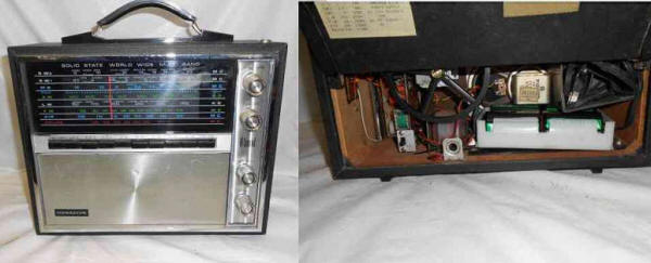
LLoyds N11B-120 Front Panel and Battery Compartment View
There are more examples of the Koyo Denki versions of this set on the
https://www.radiomuseum.org web site.
The KTR-1661 -- https://www.radiomuseum.org/r/koy_ktr_1661ktr166.html
The KTR-1662 --
https://www.radiomuseum.org/r/koyo_denki_8_band_multi_wave_ktr_1662.html
The KTR-1661 and KTR-1661 radio printed circuit boards look identical to the Lloyds 9N11B-120A
I have on the bench. The Pioneer speaker is also a good indicator of the set 's equivalence.
Thus, the Lloyds 9N11B-120A has brethren with Koyo-Denki and Commodore nameplates on their
front panels. A web search for other radios on Google image search will uncover other brands with
the same tuning wheel and front panel layout. I find “solid state 8 band radio” useful in uncovering
the variants on the image search engines.
If one wishes to order a Sams Photofact for the Lloyds radio, I will save you the search and
post the link which should take you to the appropriate page on the Sams Technical Publishing web
site.
https://www.samswebsite.com/en/Photofact/details/index/id/92920
If you have Sams TSM-139 already in your collection, you 're in luck (the service data is in
that Transistor Service Manual). TSM-139 is hard to find in the wild (i.e. ebay) so ordering the
scanned copy from Sams Technical Publishing may save you a lot of time.
The Lloyds service data on the Sams website being found, my 9N11B-120A (the radio seems identical
to the one on the Sams site although that manual is for the 9N11-120A…) is in top shape with a
new alignment (I will say, the factory alignment was still very close after 40+ years).
Flash back to the early 1970 's. Richard Nixon is president, the Cold War is in full swing,
and I had discovered my order was substituted from a Lloyds 9N11 radio to a Midland 10-561. I
remember how I studied both radios at the time and found them to be uncannily similar. With 40
years of experience under my belt, I started to apply my accumulated RF skills to the task of
finally putting all doubt on the issue to rest.
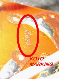
There, on the Antenna PCB Inside the Midland 10-561, YES! The Tell Tale KOYO Marking! (Now
I know how Jean-Francois Champollion felt after so many years searching and suddenly…..) |
The first step was to take the backs off of both the Lloyds 9N11 and Midland 10-561 sets. Many
similarities were noted between the two sets as I inspected them. I noticed a small “Rosetta Stone”
marking on the antenna connection PCB inside the Midland 10-561 radio (see picture below..).
The next task at hand was to compare the circuit boards in Lloyds radio to the Midland. With
the exception of the fact that the AM IF section was moved to the oscillator and band select board,
the units were very similar.
The older Lloyds unit utilized higher quality short wave band antenna matching transformers
than the Midland, but they looked to be in exactly the same places.
Annotated photographs follow showing the two sets and their similarities.
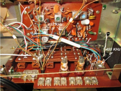
The Lloyds Receiver Noting the Position of the 455 kHz Tuning Elements.
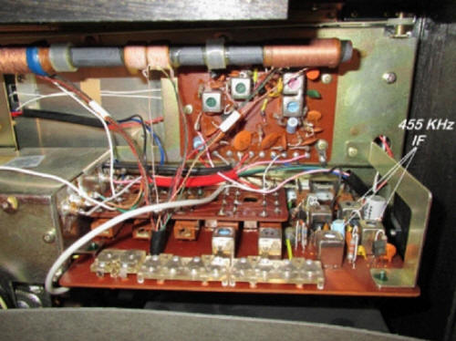
The Midland Receiver 455 kHz Tuning Elements Moved to Lower Board
Some more study of the printed circuit boards and by tuning the Midland 10-561 using the procedure
in the TSM-139 Sams document for the Lloyds confirmed my assumptions that the two radios, with
the exception of the 455 IF stages moving to the bottom PCB were almost identical electrically,
down to the location and functions of all the tuning adjustments. Even the color of the tuning
slugs called out in the Lloyds TSM-139 documentation matched the Midland slug colors EXACTLY.
To save some space and reading time, I will refer to the TSM-139 tuning procedure reference
designator call outs and annotate them for the Lloyds and the Midland sets. Bear with me on the
text call outs, my graphics program does not wrap a black line around text. I will try to make
the text as readable as possible.
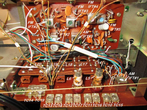
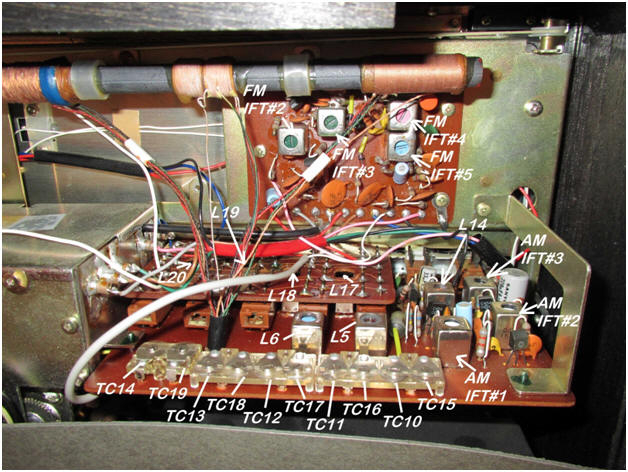
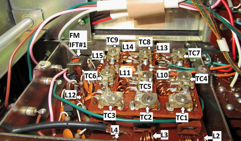
Lloyds Low Frequency RF Boards Tuning Callouts Per TSM-139
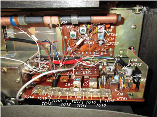
Midland 10-561 Low Frequency RF Boards Tuning Callouts Per TSM-139
I went a little lower tech with the following pictures of the high frequency boards. Microsoft
Paint (go with what works I guess) was used and I was able to make the text more readable. Arrows
added to point to the tunes as well.
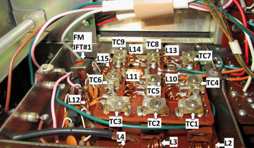
Lloyds 9N11 VHF Circuitry and Reference Designators Per TSM-139 (you have to remove the top
of the shield can to access the tuning adjustments)
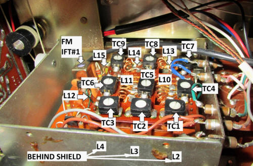
Midland 10-561 VHF Circuitry and Reference Designators Per TSM-139 (you have to remove the
top of the shield can to access the tuning adjustments)
It is clear that these two radios are very close in circuit design with possibly the Midland
radio the recipient of a cost reduction exercise.
Tuning the Midland 10-561 via the TSM-139 document with the callouts shown in the preceding
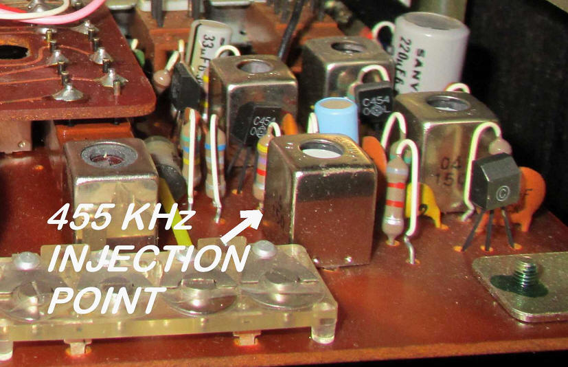
pictures worked like a charm. I did find that the section that called out the tuning of the 455
kHz section didn 't work very well with the 455 kHz signal radiated into the chassis. On the both
sets I injected the 455 kHz signal directly via a 1.8 kΩ resistor between the center pin of the
signal generator output and the point shown in the next picture. If you are tuning the Lloyds
and have the TSM-139 then it 's the base of Q8.
I also found that a good set of ears and a 400 Hz modulation tone worked better than the suggested
method of putting a meter on the speaker, but that 's just me.

455 kHz Injection Point on Midland 10-561
CONCLUSIONS
A little snooping around using Google or Bing Image Search using the brand name of the set
you are trying to resurrect and identifying text (this time “solid state 8 band” helped immensely)
will help you find the “same” radio albeit sold under another name. Using the other model number
and/or name for the set may allow you to find a schematic on the Sams web site that may not be
available for your model.
My only regret at the time of this writing is that I know, without a doubt, that there is a
Truetone version of the Midland 10-561 that is IDENTICAL (Midland and Truetone are, past a certain
date, the same U.S. company, look it up). Sams has a schematic of the Truetone radio in one of
their TSM (technical service manual)documents (I purchased it at an earlier time, but lost it
in the great hard drive crash of 2010.). When I find that link again, I 'll repost that as an
addendum to this article.
If you 're troubleshooting these transistor sets, common issues are:
- Open/dried out/ blown up electrolytic capacitors
- Sometimes leaky ones will make the radio “motorboat” at audio frequencies.
- Usually paralleling a good capacitor across the bad one while still in circuit will fix
the issue pinpointing the capacitor that needs replacement.
- Cracked PCB traces.
- Poor solder connections on the old PCB lands.
- Broken wires (especially look around battery connectors).
- Advanced techniques of Rocket Science applied with 250 Watt Weller soldering irons and globs
of solder. Reverse engineering these masterful “repairs” will usually get the set singing again
unless the patient was lost long ago without any hope of resuscitation in some dank Midwestern
basement.
And to answer my boyhood question, the Midland was “cooler looking” but as the attached photos
show, the Lloyds 9N11 was “better built” inside from the two Lloyd 's I 've rebuilt versus the
two Midland 10-561 sets. They all seem to work about the same, but I like the Lloyd 's better
as an “RF Guy.”
It would be a fun exercise for another day to replace the 455 kHz and 10.7 MHz IF filters in
these sets with nicer ones. The time spent in replacing the filters and modifying the sets would
probably be better used resurrecting a nice old Drake or Collins set (as the ARRL membership who
may have read this far would resoundingly agree).
As far as these sets future? I will let them stare down at me as I bring others back to life
in the workshop for a while and then perhaps gift them to kids I see want to carry the RF flag
into the latter half of the 21st century.
I hope this helps the reader find some answers when servicing these sets that sometimes have
little or no technical information to work from.
Until my next dissertation on rebuilding some long-lost radio aimed at preservation and possibly
keeping the large pile of e-waste from growing (at least for a few years) -- happy tuning!
This list of keywords will assist anyone using search engines for more research:
- Midland Solid State 8 Band Radio
- Truetone Solid State 8 Band Radio
- Aircastle Solid State 8 Band Radio
- Lloyds Solid State 8 Band Radio
- Commodore Solid State 8 Band Radio
- Commodore Solid State World Wide Multi Band Radio
- Midland 10-561
- Midland 10-563
- Lloyds 9N11-120A
- Lloyds 9N11A-120A
- Lloyds 9N11B-120A
- Koyo Denki KTR-1661 KTR-1662 KTR-1663 KTR-1664
- TSM-139
Posted April 14, 2014
|