[Go to TOC]
Module 1 - Introduction to Matter, Energy, and Direct Current
Pages i,
1-1,
1-11,
1-21,
1-31,
1-41,
1-51,
1-61,
2-1,
2-11,
2-21,
3-1,
3-11,
3-21,
3-31,
3-41,
3-51,
3-61,
3-71,
3-81,
3-91,
3-101,
3-111,
3-121, Appendix
I,
II,
III,
IV,
V,
Index

This process can be continued for any value resistance. You can see that as the
resistance is halved, the current is doubled; when the resistance is doubled, the
current is halved.
This illustrates another important characteristic Ohm's law - current varies
inversely with resistance when the applied voltage is held constant.
Q7. Using the graph in figure 3-7, what is the approximate value current
when the voltage is i2.5 volts?
Q8. Using the graph in figure 3-8, what is the approximate value current
when the resistance is 3 ohms?
Power
Power, whether electrical or mechanical, pertains to the rate at which work is
being done. Work is done whenever a force causes motion. When a mechanical force
is used to lift or move a weight, work is done. However, force exerted WITHOUT causing
motion, such as the force a compressed spring acting between two fixed objects,
does not constitute work.
Previously, it was shown that voltage is an electrical force, and that voltage
forces current to flow in a closed circuit. However, when voltage exists but current
does not flow because the circuit is open, no work is done. This is similar to the
spring under tension that produced no motion. When voltage causes electrons to move,
work is done. The instantaneous RATE at which this work is done is called the electric
power rate, and is measured in WATTS.
A total amount work may be done in different lengths time. For example, a given
number electrons may be moved from one point to another in 1 second or in 1 hour,
depending on the RATE at which they are moved. In both cases, total work done is
the same. However, when the work is done in a
3-11
short time, the wattage, or INSTANTANEOUS Power RATE, is greater than when the
same amount work is done over a longer period time.
As stated, the basic unit power is the watt. Power in watts is equal to the voltage
across a circuit multiplied by current through the circuit. This represents the
rate at any given instant at which work is being done. The symbol P indicates electrical
power. Thus, the basic power formula is P = E x I, where E is voltage and I is current
in the circuit. The amount power changes when either voltage or current, or both
voltage and current, are caused to change.
In practice, the ONLY factors that can be changed are voltage and resistance.
In explaining the different forms that formulas may take, current is sometimes presented
as a quantity that is changed. Remember, if current is changed, it is because either
voltage or resistance has been changed.
Figure 3-9 shows a basic circuit using a source power that can be varied from
0 to 8 volts and a graph that indicates the relationship between voltage and power.
The resistance this circuit is 2 ohms; this value does not change. Voltage (E)
is increased (by increasing the voltage source), in steps 1 volt, from 0 volts to
8 volts. By applying Ohm's law, the current (I) is determined for each step voltage.
For instance, when E is 1 volt, the current is:

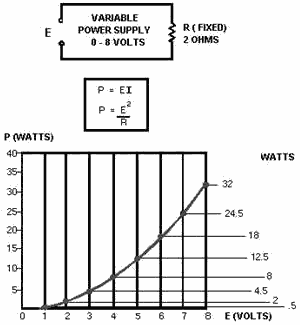
Figure 3-9. - Graph power related to changing voltage.
3-12
Power (P), in watts, is determined by applying the basic power formula:
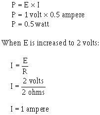
and
P = E x I
P = 2 volts x 1 ampere
P = 2 watts

You should notice that when the voltage was increased to 2 volts, the power increased
from .5 watts to 2 watts or 4 times. When the voltage increased to 3 volts, the
power increased to 4.5 watts or 9 times. This shows that if the resistance in a
circuit is held constant, the power varies directly with the SQUARE The Voltage.
Another way proving that power varies as the square the voltage when resistance
is held constant is:
3-13

Another important relationship may be seen by studying figure 3-10. Thus far,
power has been calculated with voltage and current (P = E x I), and with voltage
and resistance

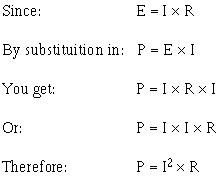
Referring to figure 3-10, note that power also varies as the square current just
as it does with voltage. Thus, another formula for power, with current and resistance
as its factors, is P = I 2R. This can be proved by:
3-14

Figure 3-10. - Graph power related to changing current.
Up to this point, four the most important electrical quantities have been discussed.
These are voltage (E), current (I), resistance (R), and power (P). You must understand
the relationships which exist among these quantities because they are used throughout
your study electricity. In the preceding paragraphs, P was expressed in terms alternate
pairs the other three basic quantities E, I, and R. In practice, you should be able
to express any one these quantities in terms any two the others.
Figure 3-11 is a summary 12 basic formulas you should know. The four quantities
E, I, R, and P are at the center the figure. Adjacent to each quantity are three
segments. Note that in each segment, the basic quantity is expressed in terms two
other basic quantities, and no two segments are alike.
3-15

Figure 3-11. - Summary basic formulas.
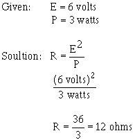
For example, the formula wheel in figure 3-11 could be used to find the formula
to solve the following problem:
A circuit has a voltage source that delivers 6 volts and the circuit uses 3 watts
power. What is the resistance the load?
Since R is the quantity you have been asked to find, look in the section the
wheel that has R in the center. The segment

contains the quantities you have been given. The formula you would use is

The problem can now be solved.
3-16
Q9. What is the term applied to the rate at which a mechanical or electrical
force causes motion?
Q1O. How can the amount current
be changed in a circuit?
Q11. What are the three formulas for
electrical power?
Power RATING
Electrical components are ten given a power rating. The power rating, in watts,
indicates the rate at which the device converts electrical energy into another form
energy, such as light, heat, or motion. An example such a rating is noted when comparing
a 150-watt lamp to a 100-watt lamp. The higher wattage rating the 150-watt lamp
indicates it is capable converting more electrical energy into light energy than
the lamp the lower rating. Other common examples devices with power ratings are
soldering irons and small electric motors.
In some electrical devices the wattage rating indicates the maximum power the
device is designed to use rather than the normal operating power. a 150-watt lamp,
for example, uses 150 watts when operated at the specified voltage printed on the
bulb. In contrast, a device such as a resistor is not normally given a voltage or
a current rating. a resistor is given a power rating in watts and can be operated
at any combination voltage and current as long as the power rating is not exceeded.
In most circuits, the actual power used by a resistor is considerably less than
the power rating the resistor because a 50% safety factor is used. For example,
if a resistor normally used 2 watts power, a resistor with a power rating 3 watts
would be used.
Resistors the same resistance value are available in different wattage values.
Carbon resistors, for example, are commonly made in wattage ratings 1/8, 1/4, 1/2,
1, and 2 watts. The larger the physical size a carbon resistor the higher the wattage
rating. This is true because a larger surface area material radiates a greater amount
heat more easily.
When resistors with wattage ratings greater than 5 watts are needed, wirewound
resistors are used. Wirewound resistors are made in values between 5 and 200 watts.
Special types wirewound resistors are used for power in excess 200 watts.
As with other electrical quantities, prefixes may be attached to the word watt
when expressing very large or very small amounts power. Some the more common these
are the kilowatt (1,000 watts), the megawatt (1,000,000 watts), and the milliwatt
(1/1,000 a watt).
Q12. What is the current in a circuit with 5 ohms resistance that uses
180 watts power? (refer to figure 3-12)
Q13. What type resistor should be used in the circuit described in question
12?
Q14. What is the power used in a circuit that has 10 amperes current through
a 10-ohm resistor?
3-17

Figure 3-12. - Circuit for computing electrical quantities.
Power CONVERSION and Efficiency
The term power consumption is common in the electrical field. It is applied to
the use power in the same sense that gasoline consumption is applied to the use
fuel in an automobile.
Another common term is power conversion. Power is used by electrical devices
and is converted from one form energy to another. An electrical motor converts electrical
energy to mechanical energy. An electric light bulb converts electrical energy into
light energy and an electric range converts electrical energy into heat energy.
Power used by electrical devices is measured in energy. This practical unit electrical
energy is equal to 1 watt power used continuously for 1 hour. The term kilowatt
hour (kWh) is used more extensively on a daily basis and is equal to 1,000 watt-hours.
The Efficiency an electrical device is the ratio power converted to useful energy
divided by the power consumed by the device. This number will always be less than
one (1.00) because the losses in any electrical device. If a device has an efficiency
rating .95, it effectively transforms 95 watts into useful energy for every 100
watts input power. The other 5 watts are lost to heat, or other losses which cannot
be used.
Calculating the amount power converted by an electrical device is a simple matter.
You need to know the length time the device is operated and the input power or horsepower
rating. Horsepower, a unit work, is ten found as a rating on electrical motors.
One horsepower is equal to 746 watts. Example: a 3/4-hp motor operates 8 hours a
day. How much power is converted by the motor per month? How many kWh does this
represent?
Given: t = 8 hrs x 30 days
P = 3/4 hp
Solution: Convert horsepower
to watts
P = hp x 746 watts
P = 3/4 x 746 watts
3-18
P = 559 watts
Convert watts to watt-hours
P = work x time
P = 559 watts x 8 x 30
P = 134,000 watt-hours per month
(Note: These figures are rounded to the nearest 1000.) To convert to kWh

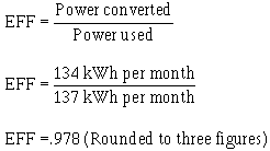
If the motor actually uses 137 kWh per month, what is the efficiency the motor?
Given: Power converted
= 134 kWh per month
Power used = 137 kWh per month
Solution:
Q15. How much power is converted by a 1-horsepower motor in 12 hours? Q16.
What is the efficiency the motor if it actually uses 9.5 kWh in 12 hours?
Series DC Circuits
When two unequal charges are connected by a conductor, a complete pathway for
current exists. An electric circuit is a complete conducting pathway. It consists
not only the conductor, but also includes the path through the voltage source. Inside
the voltage source current flows from the positive terminal, through the source,
emerging at the negative terminal.
3-19
Series Circuit Characteristics
A Series Circuit is defined as a circuit that contains only ONE PATH for current
flow. To compare the basic circuit that has been discussed and a more complex series
circuit, figure 3-13 shows
two circuits. The basic circuit has only one lamp
and the series circuit has three lamps connected in series.
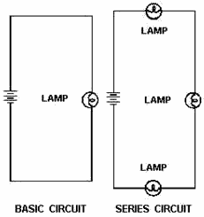
Figure 3-13. - Comparison basic and series circuits.
Resistance in a Series Circuit
Referring to figure 3-13, the current in a series circuit must flow through each
lamp to complete the electrical path in the circuit. Each additional lamp offers
added resistance. In a series circuit, The TOTAL Circuit Resistance (RT) Is EQUAL
to The SUM The INDIVIDUAL ResistanceS.
As an equation: RT = R1 + R2 + R3 + . . . R n
Note: The subscript n denotes any number additional resistances that might be
in the equation. Example: In figure 3-14 a series circuit consisting three resistors:
one 10 ohms, one 15 ohms, and one 30 ohms, is shown. a voltage source provides 110
volts. What is the total resistance?
3-20
| - |
Matter, Energy,
and Direct Current |
| - |
Alternating Current and Transformers |
| - |
Circuit Protection, Control, and Measurement |
| - |
Electrical Conductors, Wiring Techniques,
and Schematic Reading |
| - |
Generators and Motors |
| - |
Electronic Emission, Tubes, and Power Supplies |
| - |
Solid-State Devices and Power Supplies |
| - |
Amplifiers |
| - |
Wave-Generation and Wave-Shaping Circuits |
| - |
Wave Propagation, Transmission Lines, and
Antennas |
| - |
Microwave Principles |
| - |
Modulation Principles |
| - |
Introduction to Number Systems and Logic Circuits |
| - |
- Introduction to Microelectronics |
| - |
Principles of Synchros, Servos, and Gyros |
| - |
Introduction to Test Equipment |
| - |
Radio-Frequency Communications Principles |
| - |
Radar Principles |
| - |
The Technician's Handbook, Master Glossary |
| - |
Test Methods and Practices |
| - |
Introduction to Digital Computers |
| - |
Magnetic Recording |
| - |
Introduction to Fiber Optics |
| Note: Navy Electricity and Electronics Training
Series (NEETS) content is U.S. Navy property in the public domain. |


