Module 3 -- Introduction to Circuit Protection, Control, and Measurement
Pages i,
1-1,
1-11,
1-21,
1-31,
1-41,
1-51,
1-61,
1-71,
2-1,
2-11,
1-21,
2-31,
2-41,
3-1,
3-11,
3-21,
3-31,
AI-1,
AII-1,
AIII-1,
IV-1,
Index
| - |
Matter, Energy,
and Direct Current |
| - |
Alternating Current and Transformers |
| - |
Circuit Protection, Control, and Measurement |
| - |
Electrical Conductors, Wiring Techniques,
and Schematic Reading |
| - |
Generators and Motors |
| - |
Electronic Emission, Tubes, and Power Supplies |
| - |
Solid-State Devices and Power Supplies |
| - |
Amplifiers |
| - |
Wave-Generation and Wave-Shaping Circuits |
| - |
Wave Propagation, Transmission Lines, and
Antennas |
| - |
Microwave Principles |
| - |
Modulation Principles |
| - |
Introduction to Number Systems and Logic Circuits |
| - |
- Introduction to Microelectronics |
| - |
Principles of Synchros, Servos, and Gyros |
| - |
Introduction to Test Equipment |
| - |
Radio-Frequency Communications Principles |
| - |
Radar Principles |
| - |
The Technician's Handbook, Master Glossary |
| - |
Test Methods and Practices |
| - |
Introduction to Digital Computers |
| - |
Magnetic Recording |
| - |
Introduction to Fiber Optics |
| Note: Navy Electricity and Electronics Training
Series (NEETS) content is U.S. Navy property in the public domain. |
which means the fuse should be used in a circuit
where the voltage is 250 volts or less. After this is a set of three numbers and
the letter "R," which represent the current rating of the fuse. The "R" indicates
the decimal point. In the example shown, the current rating is 1R00 or 1.00 ampere.
Some other examples of the current rating are shown in the current code table of
figure 2-8. The final letter in the old military designation (A) indicates the time
delay rating of the fuse.
While the old military designation is still found on some fuses, the voltage
and current ratings must be "translated," since they use letters to represent numerical
values. The military developed the new military designations to make fuse identification
easier.
NEW MILITARY DESIGNATION
Figure 2-9 is an example of a fuse coded in the new military designation. The
fuse identified in the example in figure 2-9 is the same type as the fuse used as
an example in figure 2-8.
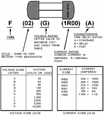
Figure 2-9. - New type military fuse designation.
The new military designation always start with the letter "F," which stands for
fuse. The set of numbers (02) next to this indicates the style. The style numbers
are identical to the ones used in the old military designation and indicate the
construction and dimensions of the fuse. Following the style designation is a single
letter (A) that indicates the time delay rating of the fuse. This is the same time
delay rating code as indicated in the old military designation, but the position
of this letter in the coding is changed to avoid confusing the "A" for standard
time delay with the "A" for ampere. Following the time delay rating is the voltage
rating of the fuse (250) V. In the old military designation, a letter was used to
indicate the voltage rating. In the new military designation, the voltage is indicated
by numbers followed by a "V," which stands for volts or less. After the voltage
rating, the current rating is given by numbers followed by the letter "A." The current
rating may be a whole number (1A), a fraction (1/500 A), a whole number and a fraction
(1 1/2A), a decimal (0.250A), or a whole number and a decimal (1.50A). If the ferrules
of the fuse are silver-plated, the current rating will be followed by the letter
"S." If any other plating is used, the current rating will be the last part of the
fuse identification.
2-11
As you can see, the new military designation is much easier to understand than
the old military designation.
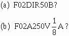
You may find a fuse coded in one of the commercial designations. The commercial
designations are fairly easy to understand and figure 2-10 shows the old and new
commercial designations for the same type of fuse that was used in figures 2-8 and
2-9.
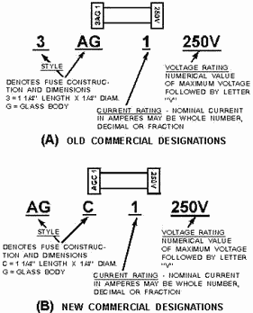
Figure 2-10. - Commercial designations for fuses
OLD COMMERCIAL DESIGNATION
Figure 2-10, view A, shows the old commercial designation for a fuse. The first
part of the designation is a combination of letters and numbers (three in all) that
indicates the style and time delay characteristics. This part of the designation
(3AG) is the information contained in the style and time delay rating portions of
military designations.
In the example shown, the code 3AG represents the same information as the underlined
portions of F02 G 1R00 a from figure 2-8 (Old Military Designation) and F02A 250VIAS
from figure 2-9 (New Military Designation). The only way to know the time delay
rating of this fuse is to look it up in the manufacturer's catalog or in a cross-reference
listing to find the military designation. The catalog will tell you the physical
size, the material from which the fuse is constructed, and the time delay rating
of the fuse. a 3AG fuse is a glass-bodied fuse, 1/4 inch x 1 1/4 inches (6.35 millimeters
x 31.8 millimeters) and has a standard time delay rating.
2-12
Following the style designation is a number that is the current rating of the
fuse (1). This could be a whole number, a fraction, a whole number and a fraction,
a decimal, or a whole number and a decimal. Following the current rating is the
voltage rating; which, in turn, is followed by the letter "V," which stands for
volts or less (250V).
NEW COMMERCIAL DESIGNATION
Figure 2-10, view B, shows the new commercial designation for fuses. It is the
same as the old commercial designation except for the style portion of the coding.
In the old commercial system, the style was a combination of letters and numbers.
In the new commercial system, only letters are used. In the example shown, 3AG in
the old system becomes AGC in the new system. Since "C" is the third letter of the
alphabet, it is used instead of the "3" used in the old system. Once again, the
only way to find out the time delay rating is to look up this coding in the manufacturer's
catalog or to use a cross-reference listing. The remainder of the new commercial
designation is exactly the same as the old commercial designation.
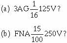
Q16. What are the voltage, current, and time delay ratings for a fuse with the
designation
Q17. What are the voltage and current ratings for a fuse designated
Q18. What is the new military designation for a fuse with the old military designation
F05A20ROB?
FUSE HOLDERS
For a fuse to be useful, it must be connected to the circuit it will protect.
Some fuses are "wired in" or soldered to the wiring of circuits, but most circuits
make use of fuse holderS. a fuse holder is a device that is wired into the circuit
and allows easy replacement of the fuse.
Fuse holders are made in many shapes and sizes, but most fuse holders are basically
either clip-type or post-type. Figure 2-11 shows a typical clip-type and post-type
fuse holder.
2-13
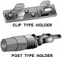
Figure 2-11. - Typical fuse holders.
CLIP-TYPE FUSE HOLDER
The clip-type fuse holder is used for cartridge fuses. The ferrules or knife
blade of the fuse are held by the spring tension of the clips. These clips provide
the electrical connection between the fuse and the circuit. If a glass-bodied fuse
is used, the fuse can be inspected visually for an open without removing the fuse
from the fuse holder. Clip-type fuse holders are made in several sizes to hold the
many styles of fuses. The clips maybe made for ferrules or knife blade cartridge
fuses. While the base of a clip-type fuse holder is made from insulating material,
the clips themselves are conductors. The current through the fuse goes through the
clips and care must be taken to not touch the clips when there is power applied.
If the clips are touched, with power applied, a severe shock or a short circuit
will occur.
POST-TYPE FUSE HOLDER
Post-type fuse holders are made for cartridge fuses. The post-type fuse holder
is much safer because the fuse and fuse connections are covered with insulating
material. The disadvantage of the post-type fuse holder is that the fuse must be
removed to visually check for an open. The post-type fuse holder has a cap that
screws onto the body of the fuse holder. The fuse is held in this cap by a spring-type
connector and, as the cap is screwed on, the fuse makes contact with the body of
the fuse holder. When the cap and fuse are removed from the body of the fuse holder,
the fuse is removed from the circuit and there is no danger of shock or short circuit
from touching the fuse.
Post-type fuse holders are usually mounted on the chassis of the equipment in
which they are used. After wires are connected to the fuse holder, insulating sleeves
are placed over the connections to reduce the possibility of a short circuit. Notice
the two connections on the post-type fuse holder of figure 2-11. The connection
on the right is called the center connector. The other connector is the outside
connector. The outside connector will be closer to the equipment chassis. (The threads
and nut shown are used to fasten the fuse holder to the chassis.) The possibility
of the outside connector coming in contact with the chassis (causing a short circuit)
is much higher than the possibility of the center conductor contacting the chassis.
The power source should always be connected to the center connector so the fuse
will open if the outside connector contacts the chassis. If the power source were
connected to the outside connector, and the outside connector contacted the chassis,
there would be a direct short, but the fuse would not open.
2-14
Q19. Label the fuse holders in figure 2-12.
Q20. Which connector should you use to connect the (a) power source and (b) load
to the fuse holder shown in figure 2-12(A)?

Figure 2-12. - Fuse holder identification.
CHECKING and REPLACEMENT of FUses
A fuse, if properly used, should not open unless something is wrong in the circuit
the fuse is protecting. When a fuse is found to be open, you must determine the
reason the fuse is open. Replacing the fuse is not enough.
Before you look for the cause of an open fuse, you must be able to determine
if the fuse is open.
CHECKING for an OPEN FUSE
There are several ways of checking for an open fuse. Some fuses and fuse holders
have indicators built in to help you find an open fuse; also, a multimeter can be used to check fuses. The simplest way to check glass-bodied fuses, and the method
you should use first, is visual inspection.
Visual Inspection
An open glass-bodied fuse can usually be found by visual inspection. Earlier
in this chapter, figures
2-4 and 2-5 showed you how an open plug-type and an open glass-bodied cartridge-type
fuse would look. If the fuse element is not complete, or if the element has been
melted onto the glass tube, the fuse is open.
It is not always possible to tell if a fuse is open by visual inspection. Fuses
with low current ratings have elements that are so small, it is sometimes not possible
to know if the fuse link is complete simply by looking at it. If the fuse is not
glass-bodied, it will not be possible to check the fuse visually. Also, sometimes
a fuse will look good, but will, in fact, be open. Therefore, while it is sometimes
possible to
know if a fuse is open by visual inspection, it is not possible to be sure a
fuse is good just by looking at it.
Fuse Indicators
Some fuses and fuse holders have built-in indicators to show when a fuse is open.
Examples of these open-fuse indicators are shown in figure 2-13. Figure 2-13, view
A, shows a cartridge-type fuse with an open-fuse indicator. The indicator is spring
loaded and held by the fuse link. If the fuse link opens, the spring forces the
indicator out. Some manufacturers color the indicator so it is easier to see in
the
open-fuse position.
2-15
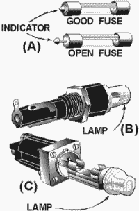
Figure 2-13. - Open fuse indicators: Clip-type fuse holder with an indicating
lamp.
Figure 2-13, view B, shows a plug-type fuse holder with an indicating lamp in
the fuse cap. If the fuse opens, the lamp in the fuse cap will light. Figure 2-13,
view C, shows a clip-type fuse holder with an indicating lamp.
Just as in visual checking, the indicator can show an open fuse. Since the indicator
may not always work, you cannot be sure a fuse is good just because there is no
open-fuse indication.
Checking Fuses with a Meter
The only sure method of determining if a fuse is open is to use a meter. An ohmmeter
can be used to check for an open fuse by removing the fuse from the circuit and
checking for continuity through the fuse (0 ohms). If the fuse is not removed from
the circuit, and the fuse is open, the ohmmeter may measure the circuit resistance.
This resistance reading might lead you to think the fuse is good. You must be careful
when you use an ohmmeter to check fuses with small current ratings (such as 1/32
ampere or less), because the current from the ohmmeter may be larger than the current
rating of the fuse. For most practical uses, a small current capacity fuse can be
checked out of the circuit through the use of a resistor. The ohmic value of the
resistor is first measured and then placed in series with the fuse. The continuity
reading on the ohmmeter should be of the same value, or close to it, as the original
value of the resistor. This method provides protection for the fuse by dropping
the voltage across the resistor. This in turn decreases the power in the form of
heat at the fuse. Remember, it is heat which melts the fuse element.
A voltmeter can also be used to check for an open fuse. The measurement is taken
between each end of the fuse and the common or ground side of the line. If voltage
is present on both sides of the fuse (from the voltage source and to the load),
the fuse is not open. Another method commonly used, is to measure across the fuse
with the voltmeter. If NO voltage is indicated on the meter, the fuse is good, (not
open).
2-16
Remember there is no voltage drop across a straight piece of wire. Some plug-type
fuse holders have test points built in to allow you to check the voltage. To check
for voltage on a clip-type fuse holder, check each of the clips. The advantage of
using a voltmeter to check for an open fuse is that the circuit does not have to
be deenergized and the fuse does not have to be removed.
Warning
PERSONNEL MAY BE EXPOSED to HAZARDOUS Voltage
Safety Precautions When Checking a Fuse
Since a fuse has current through it, you must be very careful when checking for
an open fuse to avoid being shocked or damaging the circuit. The following safety
precautions will protect you and the equipment you are using.
• Turn the power off and discharge the circuit before removing a fuse.
• use a fusepuller (an insulated tool) when you remove a fuse from a clip-type
fuse holder.
• When you check a fuse with a voltmeter, be careful to avoid shocks and short
circuits.
• When you use an ohmmeter to check fuses with low current ratings, be careful
to avoid opening the fuse by excessive current from the ohmmeter.
Q21. What are three methods for determining if a fuse is open?
Q22. You have just checked a fuse with an ohmmeter and find that the fuse is
shorted. What should you do?
Q23. You have just checked a 1/500-ampere fuse with an ohmmeter and find it is
open. Checking the replacement fuse shows the replacement fuse is open also. Why
would the replacement fuse indicate open?
Q24. How could you check a 1/500-ampere fuse with an ohmmeter?
Q25. List the safety precautions to be observed when checking fuses. REPLACEMENT
of FUses
After an open fuse is found and the trouble that caused the fuse to open has
been corrected, the fuse must be replaced. Before you replace the fuse, you must
be certain the replacement fuse is the proper type and fits correctly.
Proper Type of Replacement Fuse
To be certain a fuse is the proper type, check the technical manual for the equipment.
The parts list will show you the proper fuse identification for a replacement fuse.
Obtain the exact fuse specified, if possible, and check the identification number
of the replacement fuse against the parts list.
If you cannot obtain a direct replacement, use the following guidelines:
• Never use a fuse with a higher current rating, a lower voltage rating, or a
slower time delay rating than the specified fuse.
2-17
• The best substitution fuse is a fuse with the same current and time delay ratings
and a higher voltage rating.
• If a lower current rating or a faster time delay rating is used, the fuse may
open under normal circuit conditions.
• Substitute fuses must have the same style (physical dimensions) as the specified
fuse.
Proper Fit of Replacement Fuses
When you have obtained a proper replacement fuse, you must make certain it will
fit correctly in the fuse holder. If the fuse holder is corroded, the fuse will
not fit properly. In addition, the corrosion can cause increased resistance or heating.
Clean corroded terminals with fine sandpaper so that all corrosion is removed. Do
NOT lubricate the terminals. If the terminals are badly pitted, replace the fuse
holder. Be certain the replacement fuse holder is the correct size and type by checking
the parts list in the technical manual for the equipment.
After you check for and correct any corrosion problems, be certain the fuse fits
tightly in the fuse holder. When you insert the fuse in the cap of a plug-type fuse
holder, the fuse should fit tightly. a small amount of pressure should be needed
to insert the fuse and cap into the fuse holder body.
In clip-type fuse holders, the clips can be easily bent out of shape. This causes
an incorrect fit, which in time could cause an equipment malfunction. Figure 2-14
shows examples of correct and incorrect fuse contacts for clip-type fuse holders used with knife blade and ferrule cartridge fuses. The clips shown in the left picture
of each row have the correct contact. The three pictures on the right of each row
show incorrect contact. Notice how the clips are not contacting completely with
the knife blade or ferrules. This incomplete contact can. cause corrosion at the
contacts, which in turn can create a high resistance and drop some of the circuit
voltage at this point.
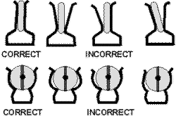
Figure 2-14. - Contact between clips and fuses.
If the fuse clips do not make complete contact with the fuse, try to bend the
clips back into shape. If the clips cannot be repaired by bending, replace the fuse
holder or use clip clamps. Clip clamps are shown in figure 2-15.
2-18
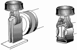
Figure 2-15. - Clip clamps.
Safety Precautions When Replacing Fuses
The following safety precautions will prevent injury to personnel and damage
to equipment. These are the MINIMUM safety precautions for replacing fuses.
• Be sure the power is off in the circuit and the circuit is discharged before
replacing a fuse.
• use an identical replacement fuse if possible.
• Remove any corrosion from the fuse holder before replacing the fuse.
• Be certain the fuse properly fits the fuse holder.
PREVENTIVE Maintenance of FUses
Preventive maintenance of fuses consists of checking for the following conditions
and correcting any discrepancies.
1. IMPROPER FUSE. Check the fuse installed against that recommended in the technical
manual for the equipment. If an incorrect fuse is installed, replace it with the
correct fuse.
2. CORROSION. Check for corrosion on the fuse holder terminals or the fuse itself.
If corrosion is present, remove it with fine sandpaper.
3. IMPROPER FIT. Check for contact between the fuse and fuse holder. If a piece
of paper will fit between the fuse and the clips on a clip-type fuse holder, there
is improper contact. If the fuse is not held in the cap of a plug-type fuse holder,
the contacts are too loose.
4. OPEN FUses. Check fuses for opens. If any fuse is open, repair the trouble
that caused the open fuse and replace the fuse.
2-19
Q26. You have removed an open fuse from a fuse holder and repaired the cause
of the fuse opening. The parts list specifies a fuse coded F02BI25VñA. There are
no fuses available with that identification.
In the following list, indicate if the fuse is a direct replacement, a good substitute,
or not
acceptable. For the fuses that are good substitutes, number them in order of
preference and explain why they are numbered that way. If the fuse is not acceptable,
explain why.
(a) F03BI25V½A
(b) F02BI25V⅜
(c) F02GR500B
(d) F02B32V½A
(e) F02DR500B
(f) F02A250V⅝
(g) F02AI25V½A
Q27. What two things should you check before replacing a fuse?
Q28. List the safety precautions to be observed when replacing a fuse.
Q29. What conditions should you check for when conducting preventive maintenance
on fuses?
Circuit BREAKERS
A circuit breaker is a circuit protection device that, like a fuse, will stop
current in the circuit if there is a direct short, excessive current, or excessive
heat. Unlike a fuse, a circuit breaker is reusable. The circuit breaker does not
have to be replaced after it has opened or broken the circuit. Instead of replacing
the circuit breaker, you reset it.
Circuit breakers can also be used as circuit control devices. By manually opening
and closing the contacts of a circuit breaker, you can switch the power on and off.
Circuit control devices will be covered in more detail in the next chapter.
Circuit breakers are available in a great variety of sizes and types. It would
not be possible to describe every type of circuit breaker in use today, but this
chapter will describe the basic types of circuit breakers and their operational
principles.
Circuit breakers have five main components, as shown in figure 2-16. The components
are the frame, the operating mechanism, the arc extinguishers and contacts, the
terminal connectors, and the trip elements.
2-20
|


