Module 6 - Introduction to Electronic Emission, Tubes, and Power
Supplies
Pages i,
1-1,
1-11,
1-21,
1-31,
1-41,
1-51,
2-1,
2-11,
2-21,
2-31,
3-1,
3-11,
3-21,
3-31,
3-41,
3-51, AI-1, Index
Chapter 2 Special-PURPOSE TUBES
Learning Objectives Upon completion of this chapter, you will be able to: 1.
Determine the number and type of individual tubes contained within the signal envelope of a multi-unit tube.
2. Explain the function and operating principle of the beam power tube and the pentode tube. 3.
State the difference between the capabilities of conventional tubes and variable-mu tubes. 4. Describe
the construction of uhf tubes, and explain the effects that ultra-high frequencies have on conventional-tube
operation. 5. Explain the operation of gas-filled diodes, thyratrons, and cold-cathode tubes.
6. Explain the operating principles behind cathode-ray tubes, and the manner in which these tubes present
visual display of electronic signals. Introduction to Special-PURPOSE TUBES
Because of their great versatility, the four basic tube types (diode, triode, tetrode, and pentode) covered
in chapter 1 have been used in the majority of electronic circuits. However, these types of tubes do have limits,
size, frequency, and power handling capabilities. Special-purpose tubes are designed to operate or perform
functions beyond the capabilities of the basic tube types discussed in chapter 1. The special-purpose tubes
covered in this chapter will include multi-unit, multi-electrode, beam power, power pentode,
variable-mu, uhf, cold cathode, thyratrons, and cathode-ray tubes.
MULTI-UNIT and MULTI-ELECTRODE TUBES One of the probems associated with electron tubes is
that they are bulky. The size of an electron tube circuit can be decreased by enclosing more than one tube within
a single envelope, as mentioned in chapter 1. There is a large variety of tubes that can be combined into this
grouping of "specialty tubes" called MULTI-UNIT tubes. Figure 2-1 illustrates the schematic
symbols of a few of the possible combinations found in multi-unit tubes. 2-1
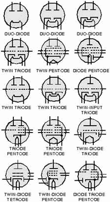
Figure 2-1. - Typical multi-unit tube symbols. An important point to remember when dealing with
multi-unit tubes is that each unit is capable of operating as a separate tube. But, how it operates, either as a
single tube or as a multi-unit tube, is determined by the external circuit wiring. When you analyze the schematic
of a circuit, simply treat each portion of a multi-unit tube as a single tube, as shown in figure 2-2.
2-2
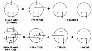
Figure 2-2. - Multi-unit tube Identification. Another type of special-purpose tube is the
MULTI-ELECTRODE tube. In some applications, tubes require more than the three grids found in conventional
tubes. In some cases, up to seven grids may be used. These types of tubes are called multi-electrode tubes and are
normally classified according to the number of grids they contain. An example of this is illustrated in figure
2-3. Here, you see a tube with five grids; hence, its name is "pentagrid." The application of these tube types
is beyond the scope of this module, but because multi-electrode tubes have been commonly used you should be aware
of their existence. 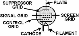
Figure 2-3. - Pentagrid multi-electrode tube. BEAM Power and Power PENTODE TUBES
The tube types you studied in the first chapter have one serious drawback; namely, they are not suitable as
power amplifiers. Because of high-plate resistance and internal construction, tubes such as the triode, tetrode,
and pentode are used only as voltage amplifiers. When power amplification is required (high-current requirements),
special-purpose tubes called Power PENTODES and BEAM Power tubes are used.
Figure 2-4 shows the arrangement of grids in a conventional pentode. The small circles depict cross sections of
the grids. Notice that each grid is offset, or staggered, from the grid directly behind it. This arrangement of
grids permits each grid to be exposed to the electron stream flowing from cathode to plate.
2-3
In this way, each grid will have maximum effect on the electron stream. There are two
undesirable effects associated with the staggered grid arrangement that make it unsuitable for use in power
amplifiers. 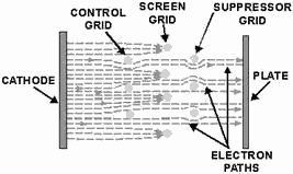
Figure 2-4. - Electron flow in a conventional pentode. First, no direct path exists between the cathode
and the plate. Electrons leaving the cathode must run an obstacle course around the grid wires to reach the plate.
Some of these electrons are deflected by the grid and scattered and, thus, never reach the plate. Second, some
electrons strike the grid wires and are removed from the electron stream as grid current. Because of these two
undesirable effects, the amount of plate current that can flow through the tube is greatly reduced. Because of
this loss of electrons from the stream, conventional tetrodes and pentodes are not suitable for power amplifiers.
Therefore, a special class of tubes has been developed to overcome this problem - the BEAM Power TUBES and
Power PENTODE TUBES. Figure 2-5 shows the cross section of the power pentode. Notice that there is no
staggered grid arrangement. Instead, each grid wire is directly in line with the grid in front of and behind it.
The screen and suppressor grids are shielded from the electron stream by the control grid. Because the screen grid
is "shielded" by the control grid, it can draw little grid current from the electron stream. 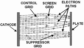
Figure 2-5. - Electron flow in a power pentode. This arrangement of grids offers few obstacles to
electron flow. Electrons will flow in "sheets" between the grid wires to the plate. The effect is to allow more of
the electrons leaving the cathode to 2-4
reach the plate. Thus, the
tube has the advantage of high power output and high efficiency. An added advantage to this type of grid
arrangement is high-power sensitivity. This means that the tube can respond to much
smaller input signals than the conventional electron tube. The reason for this is obvious; many more electrons
reach the plate from the cathode. Therefore, large plate currents can be obtained from relatively weak input
signals. Another type of power amplifier tube that is similar to the power pentode is the BEAM
Power TUBE. Beam power tubes have the same grid arrangement as the power pentodes. In addition, they use
a set of beam-forming plates to force the electron stream into concentrated beams. Figure 2-6 depicts the internal
construction of a beam-forming tube and its schematic representation. Notice that the beam- forming plates
surround the grids and their supporting structures and are internally connected to the cathode. This internal
connection ensures that the beam-forming plates are at the same negative potential as the cathode. Electrons that
are emitted from the sides of the cathode are repelled from the grid supports and into the electron stream by the
negative charge on the beam-forming plates. Electrons pass to the plate through the spaces between the
beam-forming plates and, by doing so, are concentrated into beams. Because the beam-forming plates are at a
negative potential, any electrons emitted by secondary emission are repelled back to the plate. The effect of
the beam-forming plates is to increase the number of electrons in the electron stream by forcing stray electrons
emitted from the sides of the cathode away from the grid supports and into the electron beam. Electrons that
are deflected from the grid wires are also forced into the beam. This increases the total current flowing to the
plate. For this reason, both beam-forming and power pentodes are suitable for use as power amplifiers. 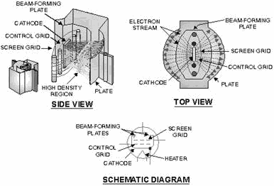
Figure 2-6. - The beam-power tube. 2-5
VARIABLE-MU TUBES In most electron-tube circuits, the operating level of a tube is
determined by the level of bias. When a negative-bias voltage is applied to the control grid of a tube, with no
input signal, the conduction through the tube is reduced; thus the damage to the tube is minimized. There is one
drawback to this. Because the control grid is already negatively charged by the bias voltage, the negative
alternation of a large input signal will drive the tube into cutoff long before the positive alternation can drive
the tube into saturation. Once the negative alternation reaches a certain level (determined by the bias voltage
and tube characteristics), the tube simply cuts off. For this reason, conventional tubes, which you previously
studied, are called SHARP-CUTofF TUBES. Because of this sharp cutoff, the range of amplification
of the conventional tube is limited by the bias voltage and tube characteristics. Once this range is exceeded, the
output becomes distorted due to cutoff. In most applications, the sharp cutoff feature of conventional
electron tubes causes no problems. However, in some applications electron tubes are required to amplify relatively
large input signals without distortion. For this reason, the variable-mu tube was developed. VARIABLE-MU
TUBES have the ability to reduce their mu, or (µ), as the input signal gets larger. As the mu (µ)
decreases, the likelihood that the tube will be driven into cutoff decreases. (For an amplifier, this may appear
to be self- defeating, but it isn't.) The idea is to amplify large input signals as much as possible without
causing the tube to cutoff or create distortion. Because of their ability to avoid being driven into cutoff,
variable-mu tubes are called REMOTE-CUTofF TUBES. You should be aware, however, that a
variable-mu tube can be driven into cutoff, but the amplitude of the input signal required to do so is
considerably greater than in conventional sharp-cutoff tubes. The key to the ability of a variable-mu tube
to decrease gain with an increase in the amplitude of the input lies in its grid construction. To
understand how the unique grid construction of a variable-mu tube works, we will first examine the grid operation
of a conventional tube during cutoff. Look at figure 2-7. Here, you see a diagram of a conventional sharp-cutoff
triode with zero volts applied to the control grid. In view A, the majority of the electrostatic lines of force
leave the positive plate (+) and travel unhindered between the evenly spaced grid wires to the negative cathode
(-). Electrons emitted by the cathode travel along these lines from the cathode, through the grid spacings, to the
plate. 2-6
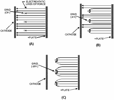
Figure 2-7. - Cutoff in a conventional tube. In view B, a bias voltage of -6 volts is applied to the
grid. As you can see, some of the electrostatic lines of force are attracted to the negatively charged grid wires
while the rest pass through the grid spacings. Because there are fewer lines of force reaching the cathode, there
are fewer paths for electrons to use to reach the plate. As a result, conduction through the tube is decreased.
In view C, the negative potential of the grid has been raised to -20 volts, which drives the tube into
cutoff. All of the electrostatic lines of force terminate at the negatively charged grid, instead of continuing on
to the cathode. The electrons emitted by the cathode will not feel the electrostatic attractive force of the
positively charged plate. Under these conditions, current cannot flow through the tube. Now look at figure
2-8. Here you see a diagram of a variable-mu, or remote-cutoff, tube. The only difference between the
remote-cutoff tube depicted and the sharp-cutoff tube is in the grid wire spacing. In the conventional
sharp-cutoff tube, the grid wires are evenly spaced, while in the remote-cutoff tube the grid wires in the middle
of the grid are placed relatively far apart. This is shown in view A. 2-7
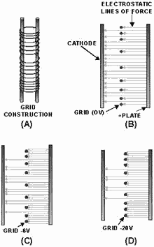
Figure 2-8. - Grid operation in a remote-cutoff tube. In view B, the control grid is at zero potential
(0 volts). Just as in the sharp-cutoff tube, electrons leave the cathode and travel along the lines of
electrostatic attraction, through the spaces between the grid wires to the plate. In view C, a bias voltage of -6
volts is applied to the grid. Because of the close spacing of the grid wires at the ends of the grid,
electrostatic lines of force at the ends are effectively terminated. The lines of force can only pass between the
widely spaced grid wires closer to the center of the grid. In view D, the same negative potential -20
volts) is applied to the grid that caused the conventional sharp-cutoff tube discussed earlier to go into cutoff.
This voltage is high enough to terminate most of the electrostatic lines of force on the grid wire. But, because
of the wide spacing between the center grid wires, some electrostatic lines of force are still able to pass
between the center grid wires and reach the cathode. Conduction will still occur in the tube, but at a reduced
level. If the grid is driven even more negative, lines of force will be blocked from reaching the cathode, except
at the very center of the grid. As you can see, the remote-cutoff tube, by its ability to reduce gain
(conduction), handles large signals without going into cutoff. a variable-mu tube such as a 6SK7 with -3 volts
applied to the grid will have a transconductance of about 2000 (µ) mhos. If the grid is driven to -35 volts, the
transconductance of the tube will decrease to 10 (µ) mhos. This same increase in negative-grid voltage would have
driven a conventional tube into cutoff long before the grid reached -35 volts. 2-8
Q1. What is the major difference in grid construction between power pentodes and conventional pentodes?
Q2. Beam-forming tubes and power tubes are similar except that power pentodes lack what element? Q3.
What effect does the shielding of the screen grid by the control grid have on plate current inbeam-forming
tetrodes? Q4. What effect does a large negative input signal applied to a variable-mu tube have on
a. conduction through the control grid, and b. gain of the tube? Q5. Identify the type of
electron tube(s) that would be most suitable for the following applications. a. Power amplifier b.
Voltage amplifier with small signal inputs c. Low distortion amplifiers for use with large signal inputs
Special UHF TUBES In the earlier discussion of
conventional-electron tubes, you learned some of the limitations of tubes. One of these limitations was that the
conventional tube was not able to operate (amplify) at extremely high frequencies such as those used in radar
equipment. Even at frequencies lower than those used in radar equipment, problems occur. For example, at ultrahigh
frequencies (300 MHz to 3000 MHz), transit time effects make the operation of a conventional-electron tube
impossible. For this reason, the special ultrahigh frequency tubes were developed to operate within this frequency
range. Before we discuss the way in which special uhf tubes counter the effects of transit time, you
should understand the manner in which transit time affects conventional tubes.
LIMITATION of TRANSIT TIME We will explain the limitation of transit time by using figure
2-9. In view A, the positive-going alternation of a uhf ac signal is applied to the grid of a conventional-triode
tube. The first positive-going alternation reduces the negative bias on the grid, and electrons start to move
toward the grid. Since the input is an ultrahigh frequency signal, the majority of the electrons cannot pass the
grid before the input signal progresses to the negative alternation. The electrons that have not yet passed the
grid are either stopped or repelled back toward the cathode. This is shown in view B. Before these electrons can
move very far, the second positive alteration reaches the grid, and causes even more electrons to move from the
cathode (view C). At the same time, the electrons that were repelled from the grid toward the cathode by the first
negative alternation feel the effect of the positive-going grid. These electrons reverse direction and again move
toward the grid. Because these electrons had to first reverse direction, they are now moving slower than the
electrons that are attracted from the cathode by the second positive alteration. The result is that the electrons
from the cathode catch up to the slower moving electrons and the two groups combine (view C). This action is
called BUNCHING. 2-9
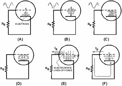
Figure 2-9. - Effect of transit time at ultrahigh frequencies. In effect, the area between the grid and
cathode becomes highly negatively charged, as shown in view D. This negative charge is surrounded by an
electrostatic field. The electrostatic field cuts the grid and repels electrons that are present in the grid. As
electrons are forced from the grid, the grid tries to go positive. Unfortunately, this tendency toward a positive
charge attracts electrons from the mass or bunched charge. Thus, as an electron is forced from the grid; it is
replaced by another from the massed charge. Electrons forced from the grid represent grid current (Ig), as shown
in view E. The grid current flows from the grid through Rg, to the cathode, from the cathode, to the massed
charged, and back again to the grid, The movement of current in this manner is, in effect, a path for current flow
from the cathode to the grid. Because current flows between the cathode and grid, the resistance (rgk) between
these elements is lowered to the point of a short circuit. The grid, in effect, is
short circuited to the cathode and ceases to function; and this, in turn, lowers tube efficiency dramatically.
This is shown in view F of figure 2-9. Transit time may be decreased by reducing the spacing between
electrodes or by increasing the electrode voltages, which in turn increases electron velocity through the tube.
The problem with the last solution is that the tube does not present an infinite resistance to current flow.
If the operating voltage is raised to an operating potential that is too high, arcing (arc over) occurs between
the cathode and the plate and, most likely, will destroy the tube. For this reason, the effects of transit time
are reduced in uhf tubes by placing the tube elements very close together. 2-10
| - |
Matter, Energy,
and Direct Current |
| - |
Alternating Current and Transformers |
| - |
Circuit Protection, Control, and Measurement |
| - |
Electrical Conductors, Wiring Techniques,
and Schematic Reading |
| - |
Generators and Motors |
| - |
Electronic Emission, Tubes, and Power Supplies |
| - |
Solid-State Devices and Power Supplies |
| - |
Amplifiers |
| - |
Wave-Generation and Wave-Shaping Circuits |
| - |
Wave Propagation, Transmission Lines, and
Antennas |
| - |
Microwave Principles |
| - |
Modulation Principles |
| - |
Introduction to Number Systems and Logic Circuits |
| - |
- Introduction to Microelectronics |
| - |
Principles of Synchros, Servos, and Gyros |
| - |
Introduction to Test Equipment |
| - |
Radio-Frequency Communications Principles |
| - |
Radar Principles |
| - |
The Technician's Handbook, Master Glossary |
| - |
Test Methods and Practices |
| - |
Introduction to Digital Computers |
| - |
Magnetic Recording |
| - |
Introduction to Fiber Optics |
| Note: Navy Electricity and Electronics Training
Series (NEETS) content is U.S. Navy property in the public domain. |
|


