Module 6 - Introduction to Electronic Emission, Tubes, and Power
Supplies
Pages i,
1-1,
1-11,
1-21,
1-31,
1-41,
1-51,
2-1,
2-11,
2-21,
2-31,
3-1,
3-11,
3-21,
3-31,
3-41,
3-51, AI-1, Index
· Place the CRT face down in an empty carton and cover its side and back with protective material.
· Carefully break off the plastic locating pin from the base (fig. 2-29) by crushing the locating pin
with a pair of pliers.
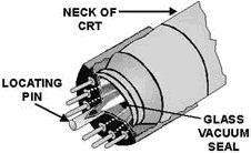
Figure 2-29. - Cathode-ray tube base structure.
· Brush the broken plastic from the pin off the CRT base.
· Look into the hole
in the base where the locator pin was. You will see the glass extension of the CRT called the vacuum seal.
Grasp the vacuum seal near the end with the pliers and crush it. This may sound a little risky but it
isn't. The vacuum seal can be crushed without shattering the tube. Once the seal has been crushed, air will rush
into the tube and eliminate the vacuum. RadioACTIVE ELECTRON TUBES Another type
of tube that can prove hazardous to you, if you handle it improperly, is the radioactive tube. These tubes
contain radioactive material and are used as voltage-regulator, gas-switching, and cold- cathode, gas-rectifier
tubes. Some of these tubes have dangerous radioactive intensity levels. Radioactive tubes are marked according to
military specifications. Radioactive material is added to a tube to aid in ionization. The radioactive
material emits relatively slowly moving particles. This should not worry you because the glass envelope is thick
enough to keep these particles inside the tube. Therefore, proper handling is nothing more than ensuring that the
envelope remains unbroken. If these tubes are broken and the radioactive material is exposed, or escapes from the
confines of the electron tube, the radioactive material becomes a potential hazard. The concentration of
radioactivity in an average collection of electron tubes in a maintenance shop does not approach a dangerous
level, and the hazards of injury from exposure are slight. However, at major supply points, the storage of large
quantities of radioactive electron tubes in a relatively small area may create a hazard. For this reason,
personnel working with equipment using electron tubes containing radioactive material, or in areas where a large
quantity of radioactive tubes are stored, should read and become thoroughly familiar with the safety practices
contained in Radiation, Health, and Protection Manual, NAVMED P-5055. Strict compliance with the prescribed safety
precautions and procedures of this manual will help to prevent accidents, and to maintain a safe working
environment which is conducive to good health. 2-31
The clean-up procedures listed below are based on NAVMED P-5055. Your ship or station may have
additional procedures that you should follow. Be sure you are aware of your command's policy concerning
decontamination procedures before you begin working on equipment containing radioactive tubes. Some important
instructions and precautions for the proper handling of radioactive tubes are listed below: 1. Do not
remove radioactive tubes from their carton until you are ready to install them. 2. When you remove a
tube containing a radioactive material from equipment, place it immediately in an appropriate carton to prevent
possible breakage. 3. Never carry a radioactive tube in a manner that may cause it to break.
4. If a radioactive tube that you are handling or removing breaks, notify the proper authority and obtain the
services of qualified radiological personnel immediately. 5. Isolate the immediate area of exposure to
protect other personnel from possible contamination and exposure. 6. Follow the established procedures
set forth in NAVMED P-5055. 7. Do not permit contaminated material to come in contact with any part of
your body. 8. Take care to avoid breathing any vapor or dust that may be released by tube breakage.
9. Wear rubber or plastic gloves at all times during cleanup and decontamination procedures.
10. use forceps to remove large fragments of a broken radioactive tube. Remove the remaining small particles
with a designated vacuum cleaner, using an approved disposal collection bag. If a vacuum cleaner is not
designated, use a wet cloth to wipe the affected area. In this case, be sure to make one stroke at a time.
DO NOT use a back-and-forth motion. After each stroke, fold the cloth in half, always holding one clean
side and using the other for the new stroke. Dispose of the cloth in the manner stated in instruction 14 below.
11. Do not bring food or drink into the contaminated area or near any radioactive material. 12.
Immediately after leaving a contaminated area, if you handled radioactive material in any way, remove all of your
clothing. Also wash your hands and arms thoroughly with soap and water, and rinse with clean water. 13.
Notify a medical officer immediately if you sustain a wound from a sharp radioactive object. If a medical officer
cannot reach the scene immediately, stimulated mild bleeding by applying pressure about the wound and by using
suction bulbs. DO NOT use YOUR MOUTH if the wound is a puncture-type wound. If the opening is
small, make an incision to promote free bleeding, and to make the wound easier to clean and flush. 14.
When you clean a contaminated area, seal all debris, cleaning cloths, and collection bags in a container such as a
plastic bag, heavy wax paper, or glass jar, and place them in a steel can until they can be disposed of according
to existing instructions. 15. use soap and water to decontaminate all tools and implements you used to
remove the radioactive substance. Monitor the tools and implements for radiation with an authorized radiac set to
ensure that they are not contaminated.
2-32
As you can see, the cleanup that results from breaking a radioactive tube is a long and complicated
procedure. You can avoid this by simply ensuring that you don't break the tube. CONVENTIONAL
TUBES
While conventional tubes present few safety problems, beyond broken glass and the possibility of cutting yourself,
there is one precaution you must know. Namely, electron tubes are hot. The filaments
of some tubes may operate at several thousand degrees. As a result, the envelopes can become very hot. When you
work on electron tube equipment, always deenergize the equipment and allow the tubes sufficient time to cool
before you remove them. If this is impossible, use special tube pullers which the Navy stocks for this purpose.
Never attempt to remove a hot tube from its socket with your bare fingers.
Summary The following summary covers the main points of this chapter. Study it to be sure you understand the material
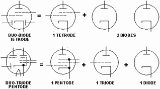
before you begin the next chapter. MULTI-UNIT TUBES were developed to reduce the size of
vacuum tube circuits. Incorporating more than one tube in the same envelope allowed the size of a vacuum tube
circuit to be reduced considerably. While a single envelope may contain two or more tubes, these tubes are
independent of each other. MULTI-ELECTRODE TUBES were developed to extend the capability
of conventional tubes. In some cases, a multi-element tube may contain up to seven grids. These types of tubes are
normally classified by the number of grids they contain.
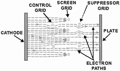
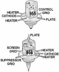
 Power PENTODES are used as current or power amplifiers. Power pentodes use in-line grid
arrangements. In this manner, more electrons can reach the plate from the cathode. In effect, this lowers plate
resistance and allows maximum conduction through the tube.
2-33
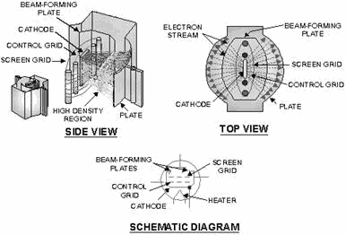
BEAM-Power TUBES are also used as power amplifiers. In addition to the in-line grid
arrangement, beam-power tubes use a set of negatively charged beam-forming plates. The beam-forming plates force
electrons that would normally be deflected from the plate back into the electron steam and, thus, add to the
number of electrons the tube can use for power amplification.
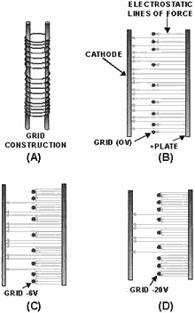
VARIABLE-MU (µ) TUBES or REMOTE-CUTofF TUBES were developed to extend the amplification
range of electron tubes by avoiding the possibility of driving the tube into cutoff. This is done by uneven
spacing of the grid wires.
2-34
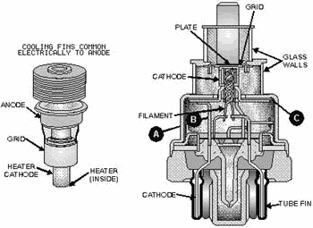
 UHF TUBES are special-purpose tubes designed to operate at ultrahigh frequencies
between 300 MHz and 3000 MHz with minimum effect from transit time limitations. Among these are acorn tubes, and
doorknob tubes, lighthouse tubes, and oilcan tubes.
2-35
PLANAR TUBES have their plates and grids mounted parallel to each other. Because of
their planar construction, they can handle large amounts of power at uhf frequencies.
GAS-FILLED TUBES contain a small amount of gas that ionizes and reduces the internal
resistance of the tubes. Because of this, gas-filled tubes can handle relatively large amounts of power while
maintaining a constant voltage drop across the tube.
2-36
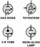
COLD-CATHODE TUBES lack heaters or filaments and, therefore, do not use thermionic
emission. Instead, a voltage potential applied across the tube causes the internal gas to ionize. Once ionization
has occurred, the voltage drop across the tube remains constant, regardless of increased conduction.
The CRT is a special-purpose tube that has the unique ability to visually display
electronic signals. The CRT uses the principles of electrostatic attraction, repulsion, and fluorescence. Because
of its unique ability, the CRT makes up the heart of many types of test equipment that you will become familiar
with during your career in electronics.
2-37

Answers to Questions Q1. Through Q18. A1. Conventional pentodes have a staggered grid arrangement, while power pentodes have a
shielded grid arrangement. A2. Beam-forming plates. A3. By increasing the number of electrons
that reach the plate, plate current is increased. A4. a large negative voltage causes conduction to
occur only at the center of the grid A5. Decreases gain. a. Power pentode or beam-forming
tetrode. b. Conventional tube. c. Variable-mu tube. A6. It causes the control grid to
short to the cathode. A7. By reducing the spacing between tube elements.
A8. The close spacing of tube elements allows for the ready formation of arcs or short circuits.
A9. Planar A10. a. They can carry more current. b. They maintain a constant IR drop
across the tube. A11. None.
A12. The filament's voltage should be applied to the tube at least 30 seconds before attempting to operate the
tube. A13. They have the ability to maintain a constant voltage drop across the tube despite changes in
current flow. A14. To visually display electronic signals.
2-38
A15. a. Electron gun. b. Deflection system c. Screen. A16.
Persistence.
A17. The horizontal-deflection plate. A18. The vertical-deflection plate.
2-39
| - |
Matter, Energy,
and Direct Current |
| - |
Alternating Current and Transformers |
| - |
Circuit Protection, Control, and Measurement |
| - |
Electrical Conductors, Wiring Techniques,
and Schematic Reading |
| - |
Generators and Motors |
| - |
Electronic Emission, Tubes, and Power Supplies |
| - |
Solid-State Devices and Power Supplies |
| - |
Amplifiers |
| - |
Wave-Generation and Wave-Shaping Circuits |
| - |
Wave Propagation, Transmission Lines, and
Antennas |
| - |
Microwave Principles |
| - |
Modulation Principles |
| - |
Introduction to Number Systems and Logic Circuits |
| - |
- Introduction to Microelectronics |
| - |
Principles of Synchros, Servos, and Gyros |
| - |
Introduction to Test Equipment |
| - |
Radio-Frequency Communications Principles |
| - |
Radar Principles |
| - |
The Technician's Handbook, Master Glossary |
| - |
Test Methods and Practices |
| - |
Introduction to Digital Computers |
| - |
Magnetic Recording |
| - |
Introduction to Fiber Optics |
| Note: Navy Electricity and Electronics Training
Series (NEETS) content is U.S. Navy property in the public domain. |
|


